Automatic optical fiber winding device

A winding device, an automatic technology, applied in the directions of transportation and packaging, conveying filamentous materials, thin material processing, etc., can solve the problems of inconvenient lateral clamping of the winding device and the influence of the winding position of the optical fiber, so as to avoid the impossible The effect of winding and avoiding excessive winding

Inactive Publication Date: 2021-06-25
芜湖信德热处理有限公司
View PDF0 Cites 1 Cited by
  • Summary
  • Abstract
  • Description
  • Claims
  • Application Information

AI Technical Summary

Problems solved by technology

[0004] The purpose of the present invention is to provide an automatic optical fiber winding device in order to solve the problem that the winding device is laterally clamped and inconvenient to take and the reel is pre-fixed and moved laterally to change the winding position of the optical fiber and affect the volume of the equipment

Method used


Image

  • Automatic optical fiber winding device
  • Automatic optical fiber winding device
  • Automatic optical fiber winding device

Examples


Embodiment Construction

[0024] The technical solutions in the embodiments of the present invention will be clearly and completely described below with reference to the accompanying drawings in the embodiments of the present invention. Obviously, the described embodiments are only a part of the embodiments of the present invention, but not all of the embodiments. Based on the embodiments of the present invention, all other embodiments obtained by those of ordinary skill in the art without creative efforts shall fall within the protection scope of the present invention.

[0025] In the description of the present invention, it should be noted that the terms "center", "upper", "lower", "left", "right", "vertical", "horizontal", "inner", "outer", etc. The indicated orientation or positional relationship is based on the orientation or positional relationship shown in the accompanying drawings, which is only for the convenience of describing the present invention and simplifying the description, rather than ...


PUM


Abstract

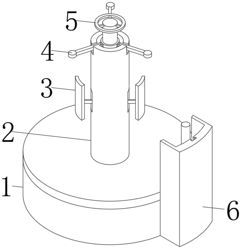
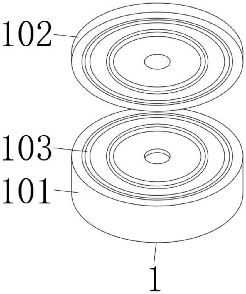
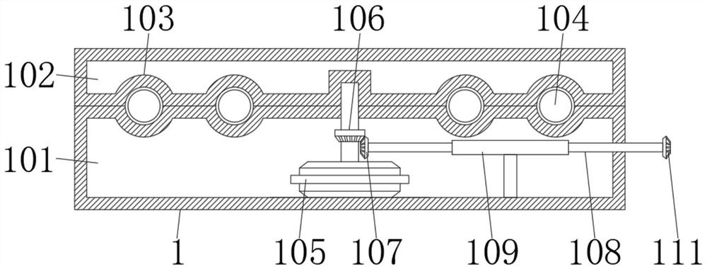
The invention discloses an automatic optical fiber winding device, and relates to the technical field of automatic optical fiber winding. The automatic optical fiber winding device comprises a base, the top end of the base is connected with a rotating column, the outer wall of the rotating column is provided with a clamping mechanism, the outer wall of the rotating column is provided with a pressing mechanism above the clamping mechanism, the top end of the rotating column is connected with a hand rotating disc, and one side of the base is connected with a direction adjusting mechanism. According to the automatic optical fiber winding device, by arranging a lifting groove, a lifting chuck, a lifting cylinder, a connector and the like, the winding position of an optical fiber is adjusted while an optical fiber winding drum conducts winding, so that a motor drives a torsion bar to rotate through a rotating rod, then the torsion bar drives a lifting rod to ascend and descend through a torsion head, and the lifting rod drives the optical fiber winding drum to ascend and descend in the lifting process; and in the lifting process of the optical fiber winding barrel, the direction of the wound light is adjusted, so that the optical fiber winding drum can drive the wound optical fiber to be subjected to direction adjustment through rotation of the lifting rod, and excessive winding of the optical fiber at the same position of the optical fiber winding drum is avoided.

Description

technical field [0001] The invention relates to the technical field of automatic optical fiber winding, in particular to an optical fiber automatic winding device. Background technique [0002] Optical fiber automatic winding device is a kind of winding equipment for optical fiber production line. The winding speed and efficiency of optical fiber can be greatly improved through the winding device. Optical fiber is generally wound by I-shaped reel. It is a limit wheel with a larger diameter, and between the two wheels is a cylinder with a relatively small diameter. The cylinder generally has a hollow structure and is used for connecting the two wheels and for the winding function of the optical fiber. [0003] The rewinding device needs to clamp the reel when rewinding. By clamping, the reel can be prevented from shaking during rewinding, which affects the rewinding effect. It is not easy to pre-fix when picked up and placed in a tight way, and even there is a risk of hand c...

Claims


Application Information

Patent Timeline
Patent Type & Authority Applications(China)
IPC IPC(8): B65H54/54B65H67/04B65H54/44B65H54/28
CPCB65H54/2818B65H54/44B65H54/54B65H67/0417B65H2701/32
Inventor 孙佰俊
Owner 芜湖信德热处理有限公司
Why Eureka
Try Eureka