a co 2 Micro blast combined with tbm rock breaking method
A CO2 and rock-breaking technology, applied in earth-moving drilling, mining equipment, tunnels, etc., can solve the problems of high blasting vibration control requirements, fast rock-breaking wear, high frequency of tool change, and achieve high construction efficiency, high safety, Continuous effect of construction
- Summary
- Abstract
- Description
- Claims
- Application Information
AI Technical Summary
Problems solved by technology
Method used
Image
Examples
Embodiment 1
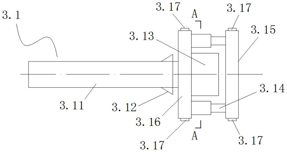
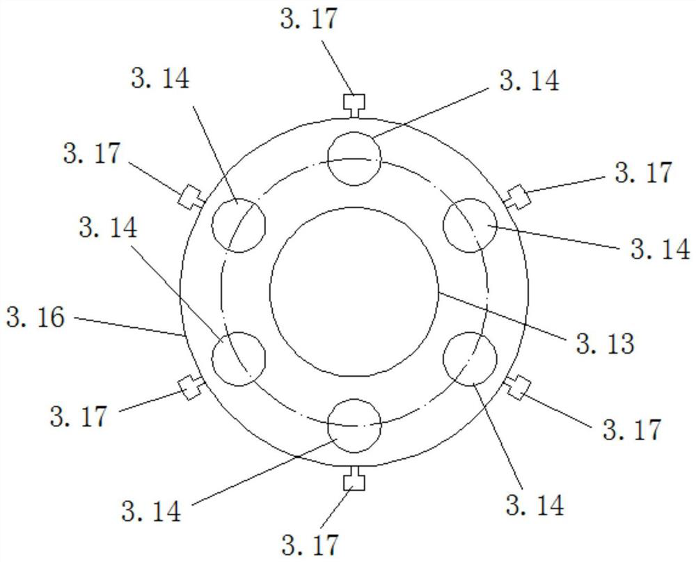
[0158] In this example, CO 2 Micro-explosion combined TBM rock breaking device 1 includes cutter head mechanism 2, drilling rig installation mechanism 3 and CO 2 Blasting device mounting mechanism 4; drilling rig mounting mechanism 3 and CO 2 The blasting device installation mechanisms 4 are alternately arranged on the cutterhead mechanism 2; the cutterhead mechanism 2 is installed on the main bearing of the TBM; the belt conveyor 5 is installed on the support frame 6;
[0159] The cutterhead mechanism 2 includes a positive cutterhead 2.1 and a side cutterhead 2.2;
[0160] The side cutter head 2.2 is located on the outer periphery of the front cutter head 2.1;
[0161] Rig mounting cylinder 3.2 and CO of rig mounting mechanism 3 2 CO of blasting device installation mechanism 4 2 The installation cylinders 4.2 are alternately arranged on the positive cutter head 2.1;
[0162] The mechanical cutter 2.11 is arranged on the positive cutterhead 2.1; the side cutterhead 2.2 is...
Embodiment 2
[0172] Its rock-breaking method is the same as embodiment 1, and the difference is that the rock mass in this embodiment is through a certain blasting and cutting, and the contour of the tunnel surface formed at last is not flat (such as Figure 30 As shown), there is a difference in the stroke of the drill pipe of the drilling rig in the rock mass.
[0173] In this embodiment, a depth measurement sensor is set on the drilling rig (being the prior art); in this embodiment, the depth data of the actual drilling of the drilling rig is obtained by the depth measurement sensor on the drilling rig, and according to the depth data, the next stage CO 2 The filling amount of the blasting device and the length of the blasting tube are adjusted; Figure 30 , the actual working footage of the drilling rigs in area A is less than the actual working footage of the drilling rigs in area B, the adjustment method in this embodiment is: in the next stage state CO 2 When blasting the device, a...
Embodiment 3
[0175] Its rock-breaking method is the same as embodiment 2, and the difference is: in the present embodiment, the tunnel face contour line is an inclined structure or a rotating structure (such as Figure 31 shown); in Figure 31 , the actual working footage of the drilling rigs in area C is greater than the actual working footage of drilling rigs in area D. The adjustment method in this embodiment is: when the TBM turns, the drilling length in area C is greater than that in area D. In the next stage, the state CO 2 When blasting the device, according to the depth of the borehole, the CO 2 The filling amount of gas is adjusted, that is, the area of C blasthole CO 2 Burst tube length and CO 2 The filling volume is larger than the D blast hole area.
[0176] Other unspecified parts belong to the prior art.
PUM
 Abstract
Description
Claims
Application Information
 - R&D
- Intellectual Property
- Life Sciences
- Materials
- Tech Scout
- Unparalleled Data Quality
- Higher Quality Content
- 60% Fewer Hallucinations
Browse by: Latest US Patents, China's latest patents, Technical Efficacy Thesaurus, Application Domain, Technology Topic, Popular Technical Reports.
© 2025 PatSnap. All rights reserved.Legal|Privacy policy|Modern Slavery Act Transparency Statement|Sitemap|About US| Contact US: help@patsnap.com


