Robot motion error in-situ detection and compensation method and equipment

A technology of robot motion and detection method, applied in the directions of manipulators, program-controlled manipulators, manufacturing tools, etc., can solve the problems of large motion errors of robots, and achieve the effect of improving motion accuracy and convenient operation

Active Publication Date: 2021-06-15
LASER FUSION RES CENT CHINA ACAD OF ENG PHYSICS
View PDF19 Cites 0 Cited by
  • Summary
  • Abstract
  • Description
  • Claims
  • Application Information

AI Technical Summary

Problems solved by technology

[0004] The purpose of the present invention is to provide a robot motion error in-position detection and compensation method and equipment, aiming to solve the technical problem of large robot motion errors in the prior art

Method used


Image

  • Robot motion error in-situ detection and compensation method and equipment
  • Robot motion error in-situ detection and compensation method and equipment
  • Robot motion error in-situ detection and compensation method and equipment

Examples


Embodiment 1

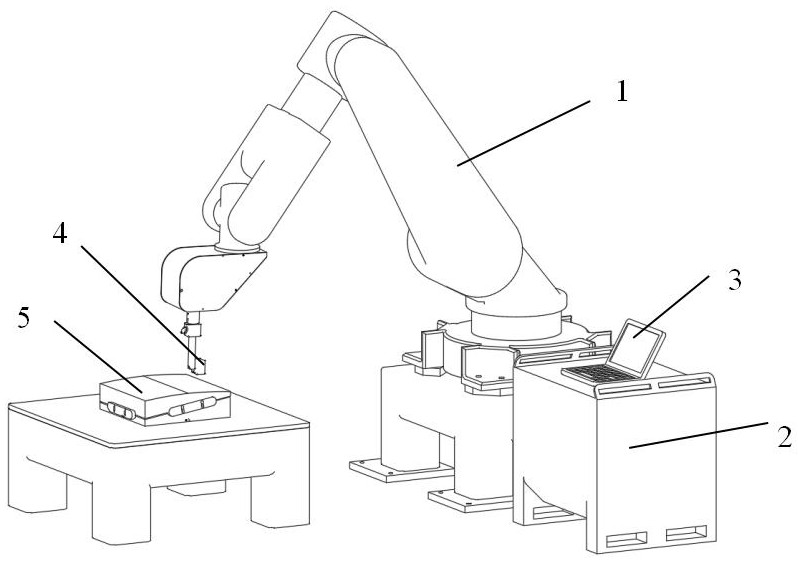
[0040] Such as figure 1 Shown is a schematic diagram of a device with a robot motion error detection and compensation function. Embodiment 1 of the present invention provides a robot with a robot motion error detection and compensation function. The device includes a robot body 1, Robot controller 2, process system 3, high-precision standard parts 5 and measuring device 4; measuring device 4 is installed at the end of robot body 1, and is electrically connected with process system 3 to realize motion error data transmission; robot controller 2 and robot body 1 , The process system 3 is electrically connected to realize program and signal transmission.

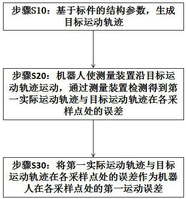
[0041] Such as figure 2 Shown is a flow chart of a robot motion error in-position detection method in the first embodiment of the present invention. A robot motion error in-position detection method in the first embodiment of the present invention includes the following steps:

[0042] Step S10: Based on the structural para...

Embodiment 2

[0067] Such as Figure 5 Shown is a flow chart of a robot motion error in-position compensation method in the second embodiment of the present invention. A robot motion error in-position compensation method in the second embodiment of the present invention includes the following steps:

[0068] Step S100: Obtain the first motion error of the robot at each sampling point by using any robot motion error in-position detection method in Embodiment 1;

[0069] Step S200: Compensate the motion error of the robot at each sampling point to the target motion trajectory to obtain the compensated motion trajectory.

[0070] Optionally, in order to verify the correctness of the robot motion error in-position compensation method in Embodiment 2 of the present invention, the following steps are also included:

[0071] Step S300: The robot makes the measuring device 4 move along the compensation trajectory. During the process of the robot moving the measuring device 4 along the compensation...


PUM


Abstract

The invention is suitable for the field of robots, and provides a robot motion error in-situ detection and compensation method and robot motion error in-situ detection and compensation equipment. The robot motion error in-situ detection method comprises the following steps that based on structural parameters of a standard part, a target motion track is generated; and a robot enables a measuring device to move along the target motion track, and in the process that the robot enables the measuring device to move along the target motion track, the actual motion error of the robot is obtained through detection of the measuring device. The motion track of the robot is compensated with error data to obtain the compensation motion track of the robot, then the motion error of the robot is restrained, and the robot motion precision is improved.

Description

technical field [0001] The invention relates to the field of advanced manufacturing technology, in particular to the field of robots, in particular to a method and equipment for in-position detection and compensation of robot motion errors. Background technique [0002] With the continuous development of modern science and technology, especially the rapid advancement of cutting-edge science and technology such as aerospace, national defense, information, microelectronics and optoelectronics, higher and higher requirements are placed on the field of ultra-precision machining. Ultra-precision manufacturing and testing technology is an important condition for realizing the batch manufacturing and production supply of ultra-precision devices. Aspherical optical components are ultra-precision devices in advanced optical systems because they are conducive to obtaining high-quality optical characteristics and high-quality image effects. [0003] In the prior art, the ultra-precisi...

Claims


Application Information

Patent Timeline
Patent Type & Authority Applications(China)
IPC IPC(8): B25J9/16B25J19/00
CPCB25J9/1628B25J19/0095
Inventor 钟波许乔陈贤华王健李海波唐耿宇邓文辉郑楠李洁
Owner LASER FUSION RES CENT CHINA ACAD OF ENG PHYSICS
Why Eureka
Try Eureka