
Aircraft flight path planning method and device capable of binding any flight path point

A trajectory planning and aircraft technology, applied in the field of flight control, can solve the problems of large trajectory tracking error, large aircraft attitude oscillation, discontinuous yaw angle command, etc., and achieve the effect of smooth trajectory

Active Publication Date: 2021-06-11
HUBEI SANJIANG AEROSPACE HONGFENG CONTROL
View PDF9 Cites 0 Cited by
  • Summary
  • Abstract
  • Description
  • Claims
  • Application Information

AI Technical Summary

Problems solved by technology

[0004] Aircraft trajectory planning has become a difficult problem in aircraft flight mission planning due to the complexity of constraint conditions and the risk cost of missions. At present, most scholars at home and abroad use graph theory to study complex environments with geometric models. However, based on geometric There are knuckles in the path of the graph or there are sharp corners that cannot be flown in the path. The maneuverability and control performance limitations of the aircraft itself often make the track tracking error large. Because the yaw angle command at the knuckle is discontinuous, the sharp corner of the planned track The attitude oscillation of the aircraft at points or knuckles is relatively large. For aircraft equipped with high-precision imaging instruments such as cameras, this attitude oscillation vibration is very unfavorable.

Method used


Image

  • Aircraft flight path planning method and device capable of binding any flight path point
  • Aircraft flight path planning method and device capable of binding any flight path point
  • Aircraft flight path planning method and device capable of binding any flight path point

Examples


Embodiment Construction

[0052] The technical solutions in the embodiments of the present application will be clearly and completely described below in conjunction with the drawings in the embodiments of the present application.

[0053] In the following introduction, the terms "first" and "second" are only used for the purpose of description, and should not be understood as indicating or implying relative importance. The following description provides multiple embodiments of the present invention, and different embodiments can be replaced or combined in combination, so the present invention can also be considered to include all possible combinations of the same and / or different embodiments described. Thus, if one embodiment contains features A, B, C, and another embodiment contains features B, D, then the invention should also be considered to include all other possible combinations containing one or more of A, B, C, D Although this embodiment may not be clearly written in the following content.

[...


PUM


Abstract

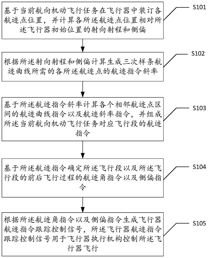
The invention discloses an aircraft flight path planning method and device capable of binding any flight path point. The method comprises the following steps: binding track point positions, and calculating the launching direction, range and lateral deviation of the track point positions; calculating the track instruction slope of the track point according to the launching direction, the range and the lateral deviation; calculating a flight path curve instruction and a flight path slope instruction of adjacent flight path point intervals based on the flight path instruction slope, and forming a flight path instruction of a flight segment corresponding to the current course maneuvering flight task; determining a flight path angle instruction and a lateral deviation instruction required by the flight task based on the flight path instruction; and generating an aircraft flight path instruction tracking control signal according to the flight path angle instruction and the lateral deviation instruction, wherein the aircraft flight path instruction tracking control signal is used for an aircraft execution mechanism to control the flight of the aircraft. According to the method, it is guaranteed that the flight path is as short as possible, the flight path is smooth, sharp points or break angles do not exist, the aircraft passes through all expected flight path points or nearby the expected flight path points in the flight path path as short as possible, and short-period obvious oscillation of the attitude angle of the aircraft is avoided.

Description

technical field [0001] The present application relates to the technical field of flight control, in particular, to an aircraft trajectory planning method and device capable of binding arbitrary trajectory points. Background technique [0002] Aircraft trajectory planning refers to planning an optimal or most satisfactory flight path for the aircraft under the premise of comprehensively considering factors such as aircraft fuel constraints, arrival time, aircraft's own mechanical properties, and control achievability, so as to ensure a successful flight path. Complete flight missions. [0003] In aircraft trajectory planning, the flight time is closely related to the fuel of the aircraft. Under the condition of satisfying other constraints, the shorter the planned trajectory, the better; the mechanical properties of the aircraft itself include the maneuverability of the aircraft itself, the Maneuverability, etc.; control achievability constraints are also very important in t...

Claims


Application Information

Patent Timeline
Patent Type & Authority Applications(China)
IPC IPC(8): G05D1/08G05D1/10
CPCG05D1/0808G05D1/101
Inventor 何昱刘冰梁云陈公仆刘成强廖良斌
Owner HUBEI SANJIANG AEROSPACE HONGFENG CONTROL
Learn More