
Balance cabin for ferris wheel

A technology of balancing cabin and Ferris wheel, applied in the direction of large runner, Russian swing, entertainment, etc., can solve the problems of small load bearing, poor eccentric load comfort, high cost, etc., to reduce equipment cost, ensure self-balancing, maintenance and replacement easy effect

Pending Publication Date: 2021-06-11
中山市金马文旅科技有限公司
View PDF0 Cites 0 Cited by
  • Summary
  • Abstract
  • Description
  • Claims
  • Application Information

AI Technical Summary

Problems solved by technology

[0003] 1. Poor vision affects passengers' experience;
[0004] 2. Poor comfort under eccentric loading. When one side is heavy, the pod will be seriously tilted, seriously affecting the comfort of passengers;
[0005] 3. The bearing load is relatively small, and the number of passengers needs to be strictly controlled, and the passenger flow cannot be increased, which will affect the turnover of the equipment;
[0006] 4. The installation needs to increase the hanging structure with the turntable, the structure is complicated, and the equipment cost is high
[0008] 1. The high cost makes many buyers give up purchasing the balance cabin Ferris wheel;
[0009] 2. The traditional balance tank generally adopts a single-ring or double-ring type, but both the single-ring and double-ring types need to use slewing bearings to realize the rotation of the balance tank. The equipment eccentric load needs to consider the resistance of the slewing bearings, and the design requirements are difficult;
[0010] 3. When the slewing bearing is damaged, it is necessary to dismantle the entire balance cabin to replace it. The replacement of the slewing bearing is more complicated and difficult; and the cost of the slewing bearing is generally about 50,000 yuan, and the maintenance cost is high

Method used


Image

  • Balance cabin for ferris wheel
  • Balance cabin for ferris wheel
  • Balance cabin for ferris wheel

Examples


Embodiment Construction

[0041] Below in conjunction with the accompanying drawings and specific embodiments, the present invention will be described in further detail:

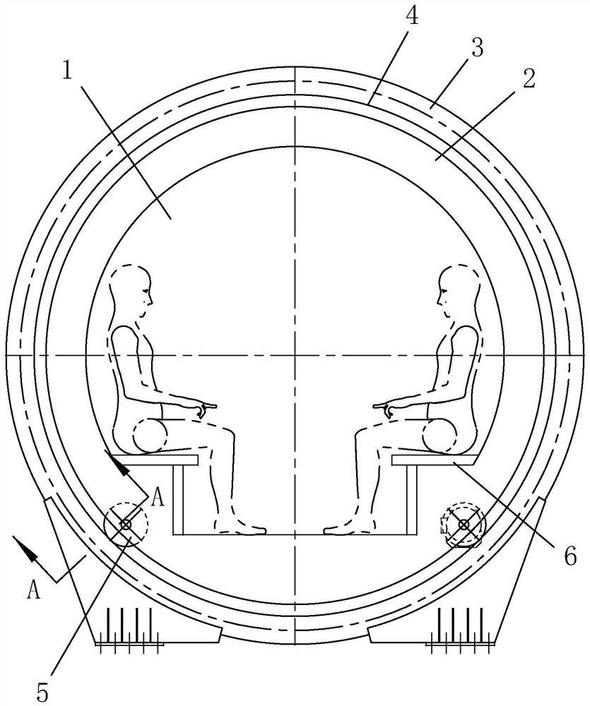
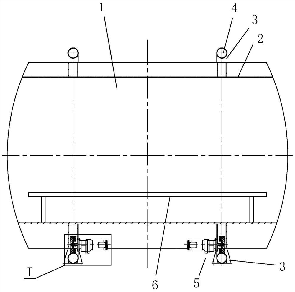
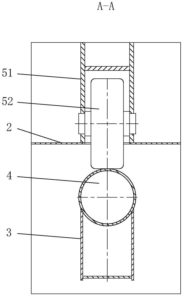
[0042] as attached figure 1 to attach Figure 12 As shown, a balance cabin for a Ferris wheel includes a rotating cabin 1, and a seat 6 for tourists is arranged inside the rotating cabin 1; at least one inner ring is sleeved on the rotating cabin 1 2. The inner ring 2 is fitted with an outer ring 3 for fixed connection with the turntable of the Ferris wheel; furthermore, the outer ring is fixedly connected with the turntable of the Ferris wheel through a flange, which saves the cockpit hanging structure, effectively Reduce equipment costs. The outer ring 3 or the inner ring 2 is provided with an arc-shaped running track 4 , and the cross section of the running track 4 is circular. The inner ring 2 or the outer ring 3 is surrounded by several wheel train components 5 which are in rolling contact with the running track 4 so that the...


PUM


Abstract

The invention relates to a balance cabin for a ferris wheel, which comprises a rotating cabin body, at least one inner ring is put on the rotating cabin body in a sleeving manner, and an outer ring fixedly connected with a turntable of the ferris wheel is sleeved on the inner ring in a sleeving manner; a walking track is arranged on the outer ring or the inner ring, and a plurality of wheel train assemblies in rolling contact with the walking track are arranged on the inner ring or the outer ring in a surrounding mode so that the inner ring of the rotating cabin can rotate relative to the outer ring. The effect of the balance cabin is achieved by adopting the design of a pod; a gear train assembly is adopted to replace a slewing bearing, so that the equipment cost is effectively reduced, and the gear train assembly is easier to maintain and replace; a wheel train assembly is provided with a power system, unbalance loading of the rotating cabin body or adverse conditions caused by other working conditions are prevented, and self-balance of the rotating cabin body can be effectively guaranteed; and the outer ring is fixedly connected with the turntable of the ferris wheel through the flange, so that a cabin hanging structure is omitted, and the equipment cost is effectively reduced.

Description

【Technical field】 [0001] The invention relates to the technical field of a Ferris wheel and a Ferris wheel cockpit, in particular to a balance cabin for a Ferris wheel. 【Background technique】 [0002] The form of ferris wheel has various in the world, but equipment cockpit is nothing more than two kinds: a kind of is suspension cabin, and another kind is balance cabin; The pod in the prior art has following shortcoming: [0003] 1. Poor vision affects passengers' experience; [0004] 2. Poor comfort under eccentric loading. When one side is heavy, the pod will be seriously tilted, seriously affecting the comfort of passengers; [0005] 3. The bearing load is relatively small, and the number of passengers needs to be strictly controlled, and the passenger flow cannot be increased, which will affect the turnover of the equipment; [0006] 4. The installation needs to increase the hanging structure with the turntable, the structure is complicated, and the equipment cost is hi...

Claims


Application Information

Patent Timeline
Patent Type & Authority Applications(China)
IPC IPC(8): A63G27/00A63G27/02
CPCA63G27/00A63G27/02
Inventor 刘喜旺王跃勇黄品伦
Owner 中山市金马文旅科技有限公司
Learn More