
Reciprocating mechanism

A technology of reciprocating motion mechanism and structure, which is applied in vibration massage, kneading massage apparatus, physical therapy and other directions, can solve the problems such as the difficulty of miniaturization of massager, increase in size of massager, power transmission loss, etc., so as to improve the use experience, Compact structure and vibration reduction effect

Pending Publication Date: 2021-06-11
SHENZHEN VINCENT TECH CO LTD
View PDF6 Cites 1 Cited by
  • Summary
  • Abstract
  • Description
  • Claims
  • Application Information

AI Technical Summary

Problems solved by technology

[0005] For the rotary reciprocating mechanism, because it contains many parts, and the installation of many parts also requires installation structure and installation space, it is not easy to miniaturize the massager, and the cooperation of multiple parts will cause power transmission. Loss, relying on the mechanical structure of friction transmission, it is easy to generate noise during the massage process
[0006] For the electromagnetic reciprocating mechanism, the axis of the electromagnetic coil and the axis of the moving part are collinear. To achieve reciprocating motion, the moving part needs to have a certain activity space in the axial direction outside the range of the electromagnetic coil for it to move back and forth. The electromagnetic reciprocating mechanism occupies a large space in its axial direction, increasing the volume of the massager

Method used


Image

  • Reciprocating mechanism
  • Reciprocating mechanism
  • Reciprocating mechanism

Examples


Embodiment Construction

[0068] In order to make the purpose, technical solutions and advantages of the embodiments of the present invention clearer, the technical solutions in the embodiments of the present invention will be clearly and completely described below in conjunction with the drawings in the embodiments of the present invention. Obviously, the described embodiments It is a part of embodiments of the present invention, but not all embodiments. The components of the embodiments of the invention generally described and illustrated in the figures herein may be arranged and designed in a variety of different configurations.

[0069] Accordingly, the following detailed description of the embodiments of the invention provided in the accompanying drawings is not intended to limit the scope of the claimed invention, but merely represents selected embodiments of the invention. Based on the embodiments of the present invention, all other embodiments obtained by persons of ordinary skill in the art wi...


PUM


Abstract

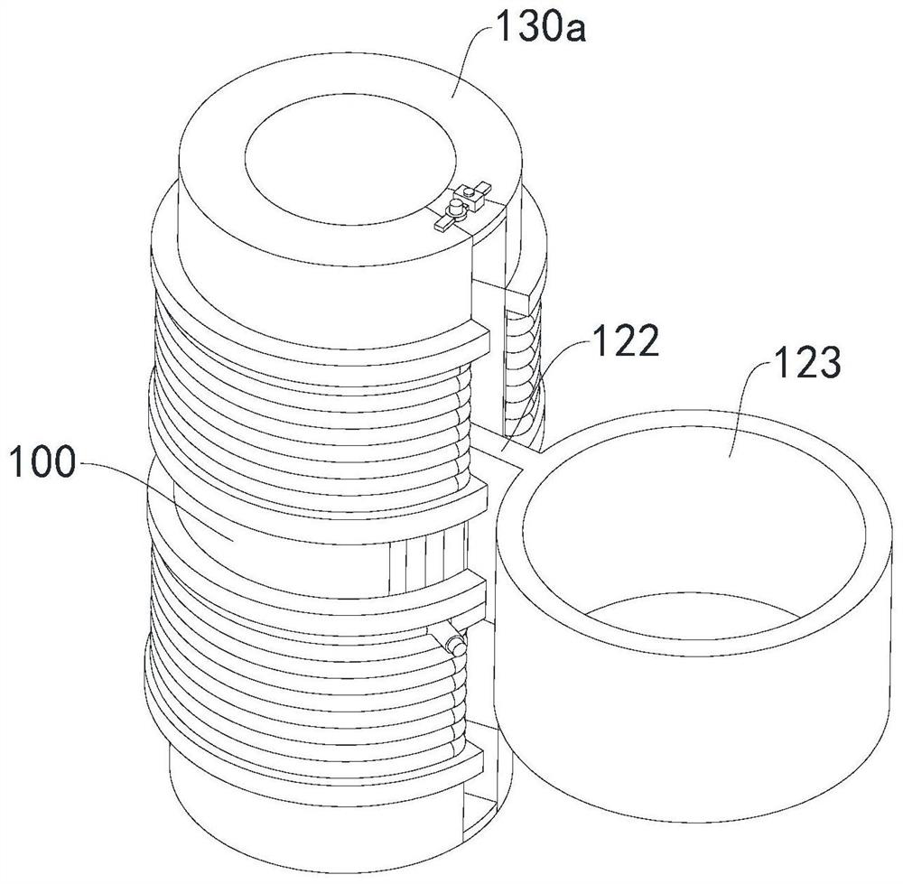
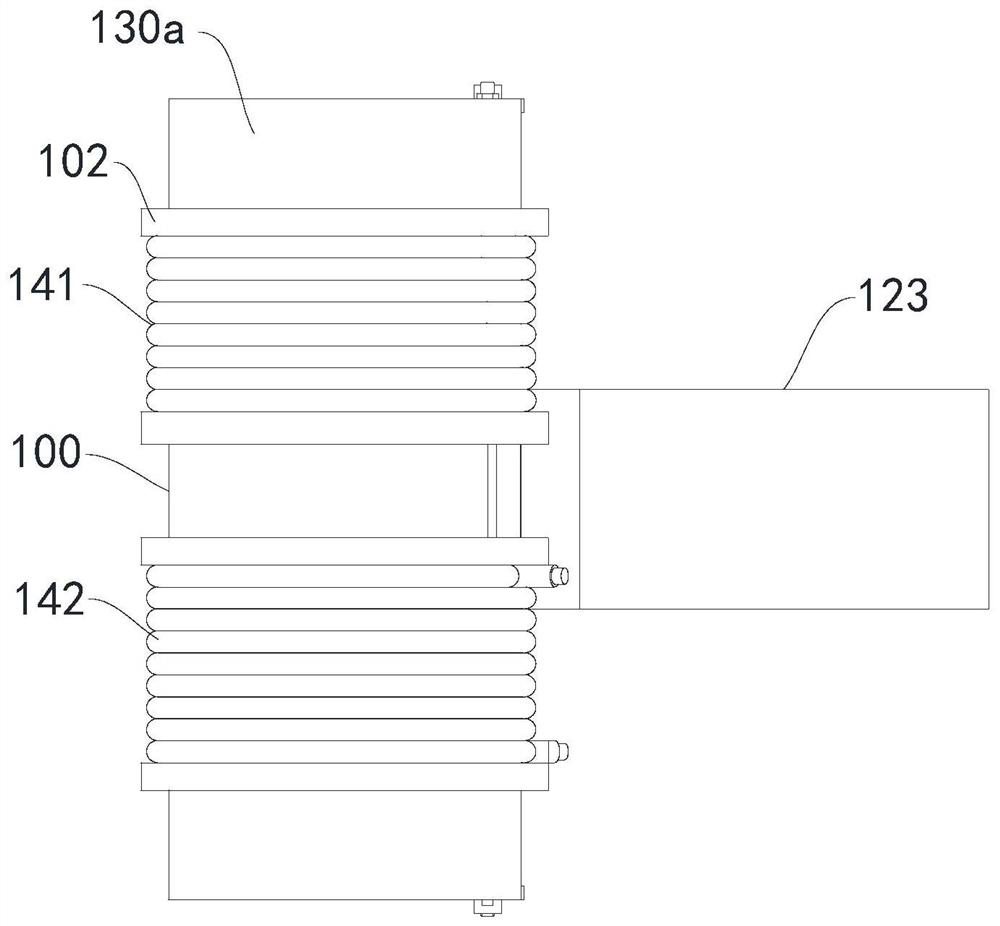
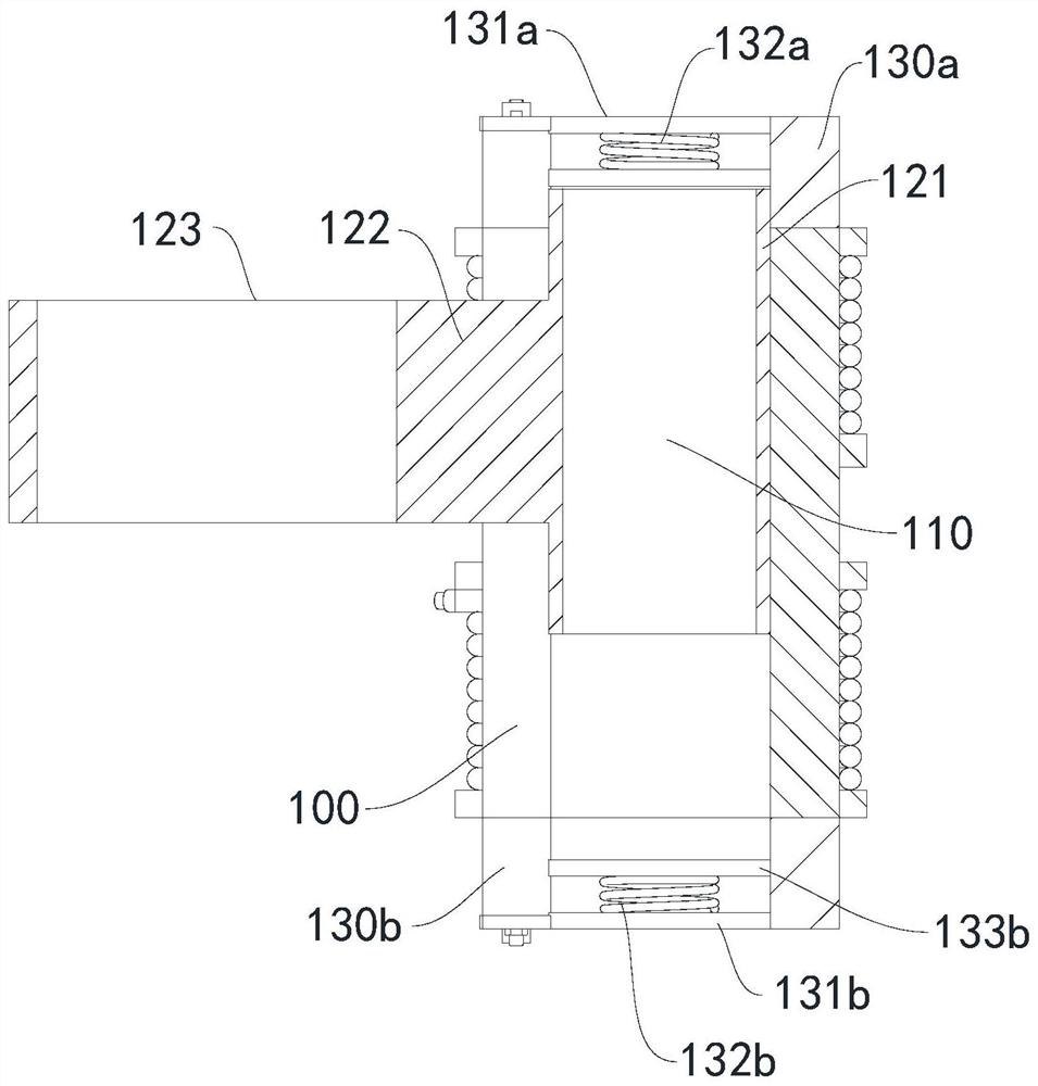
The invention provides a reciprocating mechanism. The reciprocating mechanism comprises: a base body, wherein an accommodating space is formed in the base body, and a first opening extending in the axial direction of the base body is formed in the peripheral wall of the base body; an electromagnetic coil which comprises a C-shaped first coil group and a C-shaped second coil group, the first coil group and the second coil group are respectively provided with a second opening corresponding to the first opening and are respectively wound on the periphery of the base body at an interval, the first coil group and the second coil group are communicated with each other, and when being electrified, the current direction in the first coil assembly is configured to be opposite to the current direction in the second coil assembly; a permanent magnet which is movably arranged in the accommodating space; and a connecting part, wherein one end of the connecting part is connected with the permanent magnet, and the other end of the connecting part extends to the outside of the base body through the first opening and the second opening. The reciprocating mechanism is small in length, low in noise and capable of rapidly reciprocating.

Description

technical field [0001] The invention relates to the technical field of electromagnetic conversion, in particular to a reciprocating mechanism. Background technique [0002] Reciprocating motion generally refers to the form of motion in which moving parts reciprocate along a certain trajectory from the starting point to the end point, and then from the end point to the starting point in circles to achieve the intended function. [0003] Massagers, especially massagers that require reciprocating motion, generally include rotary reciprocating mechanisms and electromagnetic reciprocating mechanisms. [0004] In the rotary reciprocating mechanism, the power source of the rotary output is converted through the mechanical structure, so that the power form is converted from the rotary motion to the reciprocating motion of the predetermined trajectory; in the electromagnetic reciprocating mechanism, the electromagnet and the permanent magnet are used. Attract and repel, causing the ...

Claims


Application Information

Patent Timeline
Patent Type & Authority Applications(China)
IPC IPC(8): A61H23/02A61H7/00
CPCA61H23/02A61H23/0218A61H7/00A61H2201/1207
Inventor 吴承锋
Owner SHENZHEN VINCENT TECH CO LTD
Learn More