
Floating prevention device for ground source heat pump buried pipe

A technology of ground source heat pump and underground pipe, which is applied in the directions of geothermal energy, geothermal energy power generation, geothermal collector, etc., can solve the problems of buried pipe depth change, floating, affecting the heat exchange efficiency of ground source heat pump, etc., and achieve the effect of preventing floating Good, easy-to-use effects

Pending Publication Date: 2021-06-08
EAST CHINA UNIV OF TECH
View PDF5 Cites 0 Cited by
  • Summary
  • Abstract
  • Description
  • Claims
  • Application Information

AI Technical Summary

Problems solved by technology

During the construction process, grouting and backfilling is required after the pipe is lowered. Due to the large amount of water slurry at the bottom of the hole and the solidification of the backfill, it takes a certain amount of time. During this time, the buried pipe has not been completely fixed, but especially for the vertical pipe The buried pipe will float up due to the buoyancy of the liquid at the bottom of the hole. Although the U-shaped bend of the buried pipe is equipped with a counterweight, the vertical pipe may be affected by the buoyancy to increase the depth of the buried pipe. The depth of the buried pipe changes, which affects the heat transfer efficiency of the ground source heat pump

Method used


Image

  • Floating prevention device for ground source heat pump buried pipe
  • Floating prevention device for ground source heat pump buried pipe
  • Floating prevention device for ground source heat pump buried pipe

Examples


Embodiment

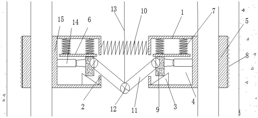
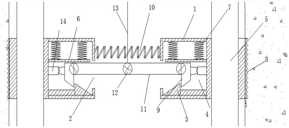
[0028] see figure 1 and Figure 4 , including a set of fixed frames 1 and a first spring 10 connecting between the fixed frames 1;

[0029] A cavity 4 is provided in the fixed frame 1, and a baffle plate 6 is horizontally provided in the cavity 4, and the baffle plate 6 is connected with the inner upper wall of the cavity 4 by a second spring 7, and the cavity 4 is A slope block 3 is provided at the bottom, and a block 9 is provided between the slope block 3 and the baffle plate 6;

[0030] One side of the stopper 9 is respectively hinged struts 11, two ends of the struts 11 away from the stopper 9 pass through the opening 2 provided on the inner cavity and are flexibly connected by a connecting shaft 12, and the other side of the stopper 9 It is connected with the side wall of the inner cavity 4 through a short rod 14;

[0031] A sling 13 is fixedly connected to the connecting shaft 12;

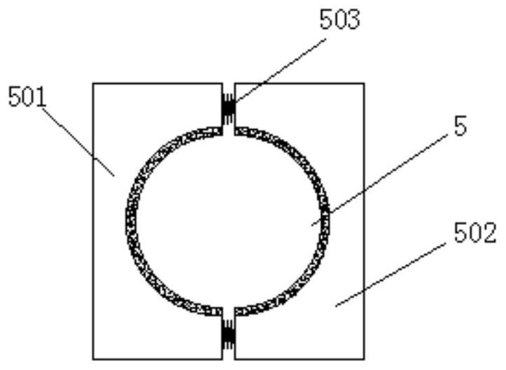
[0032] The fixed frame 1 is connected to a fixed block on the side away from it, and...


PUM


Abstract

The invention relates to a floating prevention device for a ground source heat pump buried pipe. The floating prevention device comprises a set of fixing frames and first springs connected between the fixing frames. A cavity is formed in each fixing frame, a baffle is horizontally arranged in each cavity and connected with the upper wall in the corresponding cavity through a second spring, a slope block is arranged at the bottom in each cavity, and a check block is arranged between each slope block and the corresponding baffle; one sides of the stop blocks are hinged to supporting rods respectively, the ends, away from the stop blocks, of the two supporting rods penetrate through an opening formed in an inner cavity and are movably connected through a connecting shaft, and the other sides of the stop blocks are connected with the side wall of the inner cavity through short rods; the connecting shaft is fixedly connected with a lifting rope; and the deviating side of each fixing frame is connected with a fixing block, and a through hole used for fixing the buried pipe is formed in the fixing block. When the lifting rope drives the connecting shaft at the joint of the two supporting rods to move upwards, the included angle at the joint of the supporting rods is increased, the distance between the fixing frames is increased, and the fixing blocks connected to the outer sides of the fixing frames abut against the hole wall.

Description

technical field [0001] The invention relates to the technical field of ground source heat pumps, in particular to a floating prevention device for buried pipes of ground source heat pumps. Background technique [0002] The ground source heat pump is a device that transfers low-grade heat energy to high-grade heat energy by inputting a small amount of high-grade energy (such as electric energy, etc.) from shallow terrestrial energy. Usually the ground source heat pump consumes 1kwh of energy, and the user can get more than 4kwh of heat or cold. [0003] The ground source heat pump is a heating central air conditioning system composed of a water ground source heat pump unit, a geothermal energy exchange system, and a building system, which uses rock and soil, stratum soil, groundwater or surface water as a low-temperature heat source. According to the different forms of geothermal energy exchange systems, ground source heat pump systems are divided into buried pipe ground sou...

Claims


Application Information

Patent Timeline
IPC IPC(8): F24T10/15
CPCF24T10/15F24T2010/53Y02E10/10
Inventor 郝术仁刘丽虹李明东梁海安王天源何昌春
Owner EAST CHINA UNIV OF TECH
Learn More