An automatic cutting wood cover device
A cutting device and automatic cutting technology, applied in the field of engineering, can solve problems such as low efficiency and single function, and achieve the effect of changing the speed of movement and changing the cutting effect
- Summary
- Abstract
- Description
- Claims
- Application Information
AI Technical Summary
Problems solved by technology
Method used
Image

Examples
specific Embodiment approach 1
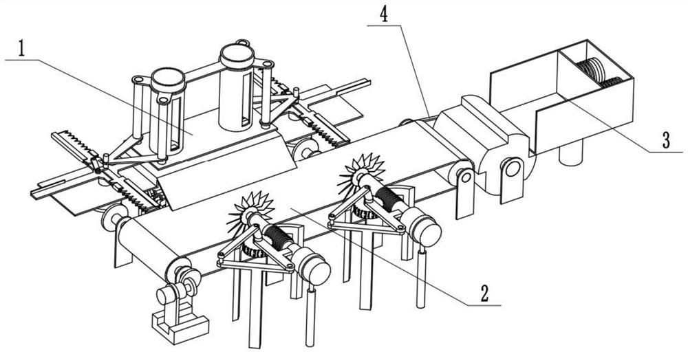
[0022] Combine below Figure 1-7 Description of this embodiment, an automatic wooden cover cutting device, including a cutting device 1, a conveying device 2, a collecting device 3, and a belt 4, the cutting device 1 is connected to the conveying device 2, and the conveying device 2 is connected to the belt 4. Connect, collecting device 3 is connected with belt one 4.
specific Embodiment approach 2
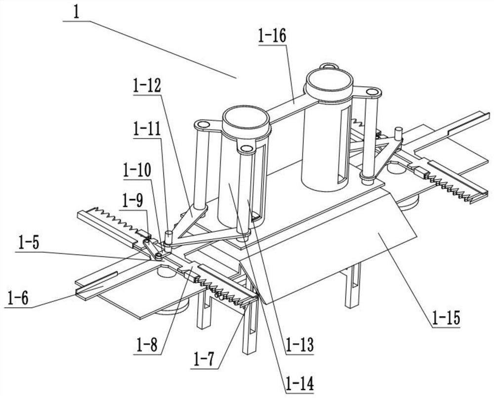
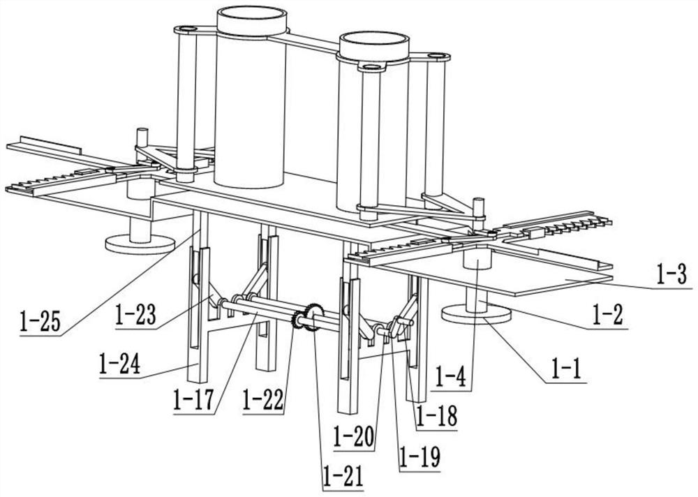
[0023] Combine below Figure 1-7 Describe this embodiment, this embodiment will further explain Embodiment 1, the cutting device 1 includes a runner 1-1, a connecting column 1-2, a boss 1-3, a hollow column 1-4, and a functional turntable 1 -5, peeling rod 1-6, lower sawtooth 1-7, upper sawtooth 1-8, connecting rod one 1-9, connecting rod two 1-10, small cylinder 1-11, fixed frame one 1-12, fixed column 1-13, feeding barrel 1-14, landslide 1-15, fixed frame 2 1-16, connecting rod 3 1-17, handle 1 1-18, handle 2 1-19, functional column 2 1-20, gear One 1-21, gear two 1-22, support rod 1-23, lower tripod 1-24, upper tripod 1-25, both sides of boss 1-3 are provided with runner one 1-1, two rotating Wheel one 1-1 is fixedly connected with connecting column one 1-2, and two connecting columns one 1-2 are all rotatably connected with hollow column 1-4, and boss 1-3 is fixedly connected with hollow column 1-4, two The connecting column 1-2 is fixedly connected with a function turnt...
specific Embodiment approach 3
[0025] Combine below Figure 1-7 Describe this embodiment, this embodiment will further explain the first embodiment, the transmission device 2 includes a motor one 2-1, a support rod two 2-2, a base 2-3, a runner three 2-4, and a runner four 2 -5, connecting column five 2-6, roller 2-7, runner five 2-8, connecting column six 2-9, runner six 2-10, belt two 2-11, runner seven 2-12, support Three 2-13, wide runner 2-14, conveyor belt 2-15, motor two 2-16, pole 2-17, connecting rod ten 2-18, connecting rod eleven 2-19, connecting rod twelve 2- 20. Screw rod 2-21, connecting rod 13 2-22, gear 3 2-23, arc frame 2-24, connecting column 10 2-25, fan 2-26, motor 1 2-1 and support rod 2 2 -2 is fixedly connected, the support rod two 2-2 is slidingly connected with the base 2-3, the motor one 2-1 is fixedly connected with the runner three 2-4, the runner three 2-4 is connected with the runner four 2-5, Runner four 2-5 is connected with connecting column five 2-6, and connecting column...
PUM
 Abstract
Description
Claims
Application Information
 - R&D
- Intellectual Property
- Life Sciences
- Materials
- Tech Scout
- Unparalleled Data Quality
- Higher Quality Content
- 60% Fewer Hallucinations
Browse by: Latest US Patents, China's latest patents, Technical Efficacy Thesaurus, Application Domain, Technology Topic, Popular Technical Reports.
© 2025 PatSnap. All rights reserved.Legal|Privacy policy|Modern Slavery Act Transparency Statement|Sitemap|About US| Contact US: help@patsnap.com