
Sewage recycling treatment equipment for municipal construction

A kind of sewage treatment equipment and technology of treatment equipment, applied in the direction of water/sewage multi-stage treatment, water/sludge/sewage treatment, flocculation/sedimentation water/sewage treatment, etc., can solve the problem of moving at any time, limited sewage, unfavorable work efficiency, etc. problems, to achieve the effect of convenient cleaning or replacement, avoiding trouble, and increasing speed

Inactive Publication Date: 2021-06-04
NANJING HANERSI BIOLOGY TECHNOLOGY CO LTD
View PDF0 Cites 0 Cited by
  • Summary
  • Abstract
  • Description
  • Claims
  • Application Information

AI Technical Summary

Problems solved by technology

[0003] Existing sewage recirculation treatment equipment is usually very large in size, and is usually fixed in a certain area to treat the sewage in this area, so that it cannot follow the municipal construction team to move at any time, while some small sewage recirculation equipment on the market The sewage that the treatment equipment can handle is limited, which cannot meet the requirements of municipal construction for sewage treatment. At the same time, most of the existing sewage recycling treatment equipment needs to manually add flocculants and coagulants, which brings some troubles to the staff. In addition, after the existing sewage recycling treatment equipment has been working for a period of time, a large amount of impurities will be generated inside the machine, and the staff need to disassemble the sewage recycling treatment equipment to remove the impurities, which is not conducive to improving work efficiency

Method used


Image

  • Sewage recycling treatment equipment for municipal construction
  • Sewage recycling treatment equipment for municipal construction
  • Sewage recycling treatment equipment for municipal construction

Examples


Embodiment 1

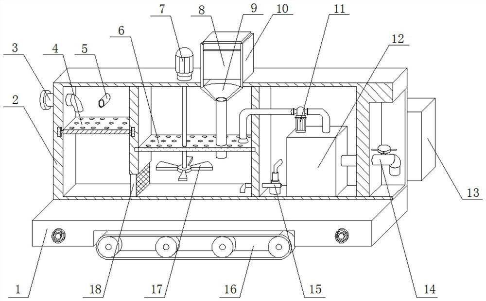
[0032] see Figure 1-Figure 8 , the present invention provides a sewage recycling treatment equipment for municipal construction, comprising a base 1, a sewage treatment equipment body 2 is fixedly installed above the base 1, a water inlet pipe 3 is fixedly installed on the upper end of the sewage treatment equipment body 2, and the water inlet pipe 3 The circulation pipe 5 is fixedly installed at the rear, the first filter plate 4 is installed movable inside the sewage treatment equipment body 2, the third filter plate 18 is fixedly installed under the first filter plate 4, and the right side of the first filter plate 4 is fixedly installed The second filter plate 6, a reagent box 10 is fixedly installed above the second filter plate 6, a funnel 9 is fixedly installed below the reagent box 10, and a hollow tube is fixedly installed below the funnel 9, and the hollow tube runs through the second filter plate 6 , the left side of the reagent box 10 is fixedly installed with the...

Embodiment 2

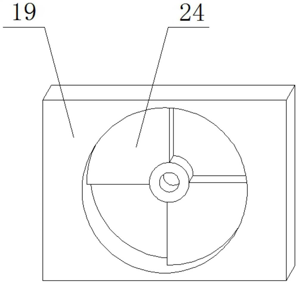
[0035] like Figure 1-6 As shown, the difference between this embodiment and Embodiment 1 is that a partition 8 is fixedly installed in the middle of the reagent box 10, and one end of the pressure sensor 22 is fixedly installed on the left and right sides below the bottom plate 19. The other end of 22 is fixedly installed on the top of fixed block 23; The inside of bottom plate 19 is fixedly installed with second baffle plate 24, and first baffle plate 21 and second baffle plate 24 are fan-shaped structures, and second motor 20 and first baffle plate The plates 21 are movably connected by a rotating shaft, and the rotating shaft runs through the second baffle plate 24; the left and right ends of the first filter plate 4 are fixedly equipped with sliders 30, the slider 30 is a T-shaped structure, and the rear of the first filter plate 4 is fixed The first spring 25 is installed, and the first filter plate 4 and the sewage treatment equipment body 2 are flexibly connected by th...

Embodiment 3

[0038] like Figure 1-8 As shown, the difference between this embodiment and Embodiments 1 and 2 is that wheels 32 are movably installed at the left and right ends of the bottom of the base 1, and the bottom surface of the wheels 32 is higher than the bottom surface of the crawler tire 16; the front of the base 1 The surface is movable with a turntable 31, and the turntable 31 and the wheel 32 are connected through a gear 34, a rack 35 and a connector 33; a circulation pipe 5 is fixedly installed at the rear upper end of the sewage treatment equipment body 2, and the circulation pipe 5 is connected to the desilting pump. 15 are connected; the rear of the sewage treatment equipment body 2 is fixedly installed with a control box 13, the control box 13 and the pressure sensor 22 are connected by signals, and the control box 13 controls the first motor 7, the water pump 11, the desilting pump 15 and the second Motor 20.

[0039] In this embodiment, because the environment of muni...


PUM


Abstract

The invention discloses sewage recycling treatment equipment for municipal construction. The sewage recycling treatment equipment comprises a base, a sewage treatment equipment body is fixedly mounted above the base, and a water inlet pipe is fixedly mounted at the upper end of the sewage treatment equipment body. The equipment is provided with a second motor and pressure sensors. The second motor is movably connected with a first baffle through a rotating shaft, the second motor can drive the first baffle to rotate, the first baffle and a second baffle can control falling of a flocculating agent and a coagulant aid in a reagent box, and the pressure sensors are fixedly installed on the left side and the right side of the lower portion of a bottom plate. The weight of reagents above the bottom plate can be measured in real time through the pressure sensors, the falling weight of the flocculating agent and the coagulant aid can be calculated by adopting a method of subtracting the weight at the moment from the initial weight, and the process of automatically adding the reagent can be completed through the second motor and the pressure sensors, so that the trouble of manually adding the reagent is avoided, and the sewage treatment efficiency is improved.

Description

technical field [0001] The invention belongs to the technical field of sewage treatment equipment, and in particular relates to sewage recycling treatment equipment for municipal construction. Background technique [0002] With the development of society, the demand for fresh water in all walks of life is increasing. my country is one of the countries that lack water resources, but every municipal construction requires a large amount of fresh water. Through sewage treatment equipment, the A series of purification and filtration of used fresh water can not only effectively prevent sewage and pollutants from flowing directly into rivers and other waters or seep into the ground, but also purify the treated sewage to meet the quality requirements of reuse water, so as to achieve the recycling of water purpose of the resource. [0003] Existing sewage recirculation treatment equipment is usually very large in size, and is usually fixed in a certain area to treat the sewage in this...

Claims


Application Information

Patent Timeline
IPC IPC(8): C02F9/04B01D29/03B01D29/56B01D29/96C02F1/50C02F1/52
CPCB01D29/03B01D29/56B01D29/96C02F1/50C02F1/52C02F9/00C02F2209/03C02F2301/08
Inventor 李新军吴红超张力
Owner NANJING HANERSI BIOLOGY TECHNOLOGY CO LTD
Learn More