Electric flocculation device

A technology of electrocoagulation and conductive rods, which is applied in water/sewage treatment, water/sludge/sewage treatment, chemical instruments and methods, etc. It can solve problems such as electrolysis blockage, slowing down of electrocoagulation speed, and reduction of flocculation efficiency. Achieve the effects of increasing the current intensity, increasing the electrocoagulation speed, and compensating the resistance

Pending Publication Date: 2021-06-04
左海霞
View PDF0 Cites 0 Cited by
  • Summary
  • Abstract
  • Description
  • Claims
  • Application Information

AI Technical Summary

Problems solved by technology

[0003] First of all, in the process of electrocoagulation, strong reducing new ecological hydrogen will be produced on the cathode, which can have a reduction reaction with the pollutants in the wastewater or generate hydrogen gas, and together with the oxygen bubbles generated by the anode, fully interact with the suspended flocculation particles Contact, so as to obtain good adhesion performance, which is beneficial to the removal of pollutants, but because the bubbles are affected by the buoyancy of water and float upward, and the gas generated near the upper plate floats upward, it is easy to make the bubbles be adsorbed on the upper plate. In this way, the electrode plate is covered, so that the effective electrolysis area between the two electrode plates is reduced, and then the flocculation efficiency is continuously reduced during the electrocoagulation process.
[0004] Secondly, in the process of electrocoagulation, the thickness of suspended particles after flocculation increases continuously, and the electrolysis between the two plates needs to pass through the pollutants under flocculation in the middle, and the thickness of pollutants continues to increase, which hinders electrolysis, which in turn causes the speed of electrocoagulation to slow down. slow

Method used


Image

  • Electric flocculation device
  • Electric flocculation device
  • Electric flocculation device

Examples


Embodiment Construction

[0020] The following will clearly and completely describe the technical solutions in the embodiments of the present invention with reference to the accompanying drawings in the embodiments of the present invention. Obviously, the described embodiments are only some, not all, embodiments of the present invention. Based on the embodiments of the present invention, all other embodiments obtained by persons of ordinary skill in the art without making creative efforts belong to the protection scope of the present invention.

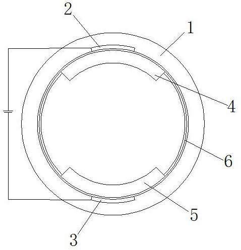
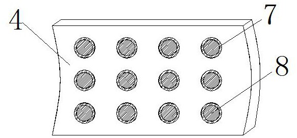
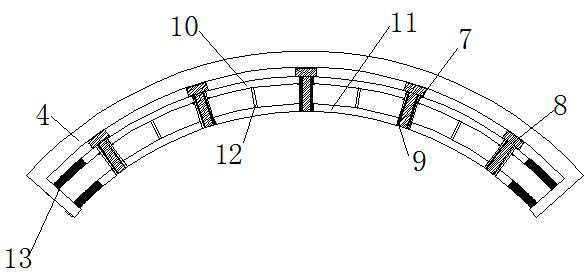
[0021] see Figure 1-4 , an electroflocculation device, comprising a casing 1, an upper contact 2 is fixedly installed on the upper surface inside the casing 1, a lower contact 3 is fixedly installed on the lower surface inside the casing 1, and the inner movable socket of the casing 1 There is an anode plate 4 located below the upper contact 2, and a cathode plate 5 located above the lower contact 3 is movably socketed inside the casing 1. After the plate con...


PUM


Abstract

The invention relates to the technical field of wastewater treatment, and discloses an electric flocculation device, which comprises a machine shell, an upper contact is fixedly installed on the upper surface in the machine shell, a lower contact is fixedly installed on the lower surface in the machine shell, an anode plate located below the upper contact is movably connected into the machine shell in a sleeved mode, a cathode plate located above the lower contact is movably connected into the machine shell in a sleeved mode, connecting rings are fixedly installed on the two sides of an anode plate and the two sides of the cathode plate, and an outer bent plate is movably installed at the bottom of the anode plate. According to the electric flocculation device, after bubbles adhere to the periphery of a conductive rod, the water pressure borne by an outer sleeve is reduced at the moment, the outer sleeve moves downwards, the lower end of a gas channel is exposed in the bubbles, the outer portions of the bubbles enter the upper portion of an inner bent plate under the action of the water pressure at the moment, a conductive rod is always exposed in wastewater, and a maximum electrolysis area is kept, therefore, in the electric flocculation process, the flocculation speed is not influenced by water electrolysis.

Description

technical field [0001] The invention relates to the technical field of wastewater treatment, in particular to an electrocoagulation device. Background technique [0002] Electrocoagulation technology has the characteristics of electrochemical oxidation, flocculation and air flotation. It is favored in wastewater treatment because of its small sludge output, no addition of chemicals, simple equipment and operation. Its working principle is that wastewater enters the electrocoagulation device. An electrochemical reaction occurs between the upper and lower plates, causing the pollutants in the wastewater to flocculate. [0003] First of all, in the process of electrocoagulation, strong reducing new ecological hydrogen will be produced on the cathode, which can have a reduction reaction with the pollutants in the wastewater or generate hydrogen gas, and together with the oxygen bubbles generated by the anode, fully interact with the suspended flocculation particles Contact, so ...

Claims


Application Information

Patent Timeline
Patent Type & Authority Applications(China)
IPC IPC(8): C02F1/463
CPCC02F1/46109C02F1/463C02F2001/46128C02F2201/4619
Inventor 左海霞
Owner 左海霞
Why Eureka
Try Eureka