
Omnibearing docking system and method based on flight array

An all-round, array technology, applied in the direction of aircraft, convertible aircraft, aircraft parts, etc., can solve the problems of non-face-to-face docking, position cannot be accurately determined, poor connection rigidity, etc., to achieve efficient docking and locking tasks, good Simple effects of standard features, part features

Active Publication Date: 2021-06-04
XIDIAN UNIV
View PDF9 Cites 1 Cited by
  • Summary
  • Abstract
  • Description
  • Claims
  • Application Information

AI Technical Summary

Problems solved by technology

[0008] (1) The existing aerial docking mechanism has a long axial distance, the docking action is discontinuous, and the position cannot be accurately determined
In addition, guiding the active docking device through the guide surface has the interference of collision, which is easy to cause mechanical loss of parts
[0009] (2) The docking mechanism based on electromagnetic characteristics can only complete the docking task directly opposite, and the docking performance of the system is poor
[0010] (3) The docking mechanism based on the docking claw uses the docking claw for structural locking. The movement plane of the claw can only be perpendicular to the docking surface, and it does not have the ability to dock non-directly.
[0011] (4) Most of the existing aerial UAV docking systems take up a lot of space, the connection rigidity is poor, and the docking gap is large, resulting in loose collisions between UAVs due to relative speed
Does not have the ability to work in small spaces, high rigidity, and reliable electrical connections

Method used


Image

  • Omnibearing docking system and method based on flight array
  • Omnibearing docking system and method based on flight array
  • Omnibearing docking system and method based on flight array

Examples


Embodiment Construction

[0054] In order to make the object, technical solution and advantages of the present invention more clear, the present invention will be further described in detail below in conjunction with the examples. It should be understood that the specific embodiments described here are only used to explain the present invention, not to limit the present invention.

[0055] Aiming at the problems existing in the prior art, the present invention provides an all-round docking system and method based on flight arrays. The present invention will be described in detail below with reference to the accompanying drawings.

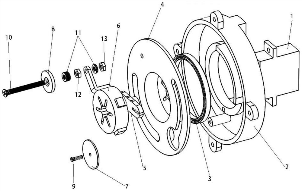
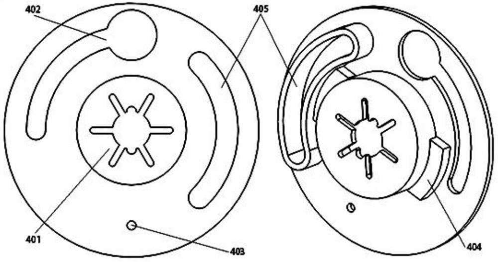
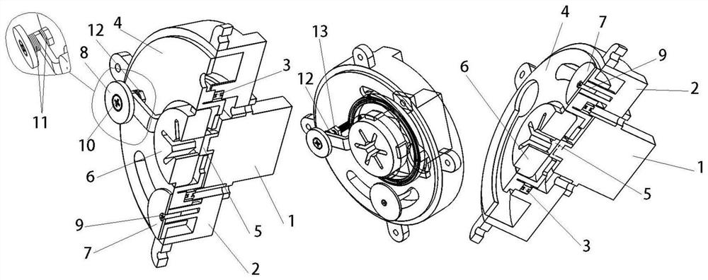
[0056] like figure 1 As shown, the omnidirectional docking system based on the flight array provided by the embodiment of the present invention includes a driving steering gear 1, a docking housing 2, a bearing ring 3, a locking track ring 4, a steering gear arm 5, a buffer block 6, and a fixing ring gasket 7 , Locking rubber 8, fixing ring gasket screw 9, locking rubber sc...


PUM


Abstract

The invention belongs to the technical field of space docking, and discloses an omnibearing docking system and method based on flight array. The outer end of a docking shell is fixedly provided with a driving steering engine through screws, the docking shell is cylindrical, the interior of the docking shell is hollow and serves as a steering engine rotating space, and a bearing ring is installed in the middle of the docking shell; a locking track ring is mounted on the inner ring of the bearing ring, and the inner side of the locking track ring is fixedly connected with a steering engine arm through a plurality of screws; a buffer block is mounted in a recess in the middle of the locking track ring, and is connected with the steering engine arm and the locking track ring through screws; and the side face of the buffer block is connected with the locking track ring through a fixing assembly. The system has obvious non-front-face butt joint capability, can realize structural locking between non-front faces of a flight array, and has the advantages of reliable connection, small occupied space and the like; and docking mechanisms are not active and passive, the two docking mechanisms are identical in structure and control principle except for the opposite rotation directions of the steering engines, and the uniformity of topological structures is achieved.

Description

technical field [0001] The invention belongs to the technical field of space docking, and in particular relates to an all-round docking system and method based on flight arrays. Background technique [0002] At present: the development and application of UAV aerial docking has attracted great attention from various countries. People have put forward more requirements on the UAV's airborne time, information transmission between UAVs and the load of UAVs, and the modular design of operating units. high demands. Among them, the flight system composed of multiple UAVs is called a flight array. It is necessary to ensure a reliable docking relationship between any two units in the flight array, and sometimes the docking mechanism is required to have the ability to dock non-directly. The so-called non-directly opposite refers to: when the UAV forms an air array, all the surfaces other than the corresponding surface where the docking action occurs, its function is to ensure the re...

Claims


Application Information

Patent Timeline
IPC IPC(8): B64C37/02B64C7/00
CPCB64C37/02B64C7/00
Inventor 张树新姜伟涛王耀华段宝岩
Owner XIDIAN UNIV
Learn More