Method for preventing middle roller way strip steel from rising

An intermediate roll and strip technology, applied in the field of steel rolling in the metallurgical industry, can solve the problems of insufficient intervention, excessive intervention, strip narrowing, etc., and achieve the effect of reducing frequent adjustments, preventing slippage, and ensuring rolling stability.

Active Publication Date: 2021-06-04
TANGSHAN IRON & STEEL GROUP +1
View PDF6 Cites 0 Cited by
  • Summary
  • Abstract
  • Description
  • Claims
  • Application Information

AI Technical Summary

Problems solved by technology

[0004] (1) The accuracy of tension calculation is low, and it cannot reflect the actual tension of the strip length, especially in the second half of the strip, often the calculated tension has reached the set tension, but the actual strip phenomenon occurs;
[0005] (2) The method of manually identifying strip sheathing in the middle roller table lags behind seriously. When the operator recognizes the strip sheathing, the amount of strip sheathing is often already serious, and the interpretation of strip sheathing by different people is inconsistent. There is a certain difference, and the recognition accuracy is not high;
[0006] (3) After the operator recognizes the strip sheathing of the middle roller table, it generally uses manual intervention on the speed of the rough rolling end stand to suppress the sheathing of the strip steel. The manual intervention control effect is poor, and there are problems of insufficient intervention and excessive intervention. Insufficient intervention If the phenomenon of strip sheathing cannot be improved, excessive intervention will lead to excessive strip tension in the middle roller table, which will eventually lead to strip narrowing and product width quality problems

Method used


Image

  • Method for preventing middle roller way strip steel from rising
  • Method for preventing middle roller way strip steel from rising
  • Method for preventing middle roller way strip steel from rising

Examples


Embodiment Construction

[0026] Below in conjunction with the accompanying drawings, the present invention will be further described by examples.

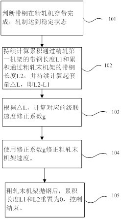
[0027] Refer to the attached Figure 1-4 , a method to prevent the middle roller strip from rising up, follow the steps below:

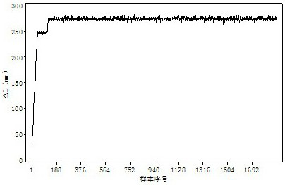
[0028] (1) After the finishing stand is bitten and delayed for a period of time, the cumulative strip length L1 passing through the first finishing stand and the cumulative strip length L2 passing through the rough rolling stand are continuously calculated, and the calculation is continued. The starting amount △L, namely L2-L1;

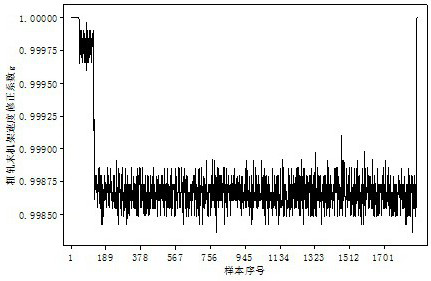
[0029] (2) According to △L, calculate the lifting rate e. The lifting rate e is the ratio of the lifting amount △L to the length L of the final rack of rough rolling and the first rack of finishing rolling, namely:

[0030] e=△L / L

[0031] (3) Set the control dead zone value Ɛ, the value range of Ɛ is 0~0.015, when the lifting rate e is less than or equal to the control dead zone value Ɛ, the correcti...


PUM


Abstract

The invention relates to a method for preventing middle roller way strip steel from rising, and belongs to the technical field of steel rolling in the metallurgical industry. According to the technical scheme, the method comprises the following steps of (1) calculating the loop rising amount delta L, namely L2-L1; (2) calculating the loop rising rate e, wherein e is equal to delta L / L; (3) calculating a cascade speed correction coefficient g of a rough rolling end rack; and (4) correcting the speed of the rough rolling end rack by using the correction coefficient g, specifically, after loop rising of the middle roller way strip steel is judged and the cascade speed correction coefficient g of the rough rolling end rack is calculated, checking the upper limit and the lower limit of the correction coefficient g before the speed of the rough rolling end rack is corrected, and multiplying the correction coefficient g after the limit check by a speed set value of the rough rolling end rack to achieve a new speed setting for adjusting the rough rolling end rack so as to prevent the middle roller way strip steel from rising. The method has the beneficial effects that the loop rising condition of the middle roller way strip steel is judged through a logical algorithm, and then the speed of the rough rolling end rack is corrected, so that the purpose of preventing loop rising of the middle roller way strip steel is achieved.

Description

technical field [0001] The invention relates to a method for preventing strip steel from being pulled up in an intermediate roller table, and belongs to the technical field of steel rolling in the metallurgical industry. Background technique [0002] In the field of steel rolling technology, especially in the production process of short-flow hot rolling, the head of the strip comes out of the rough rolling stand, passes through the intermediate roller table, and enters the finishing mill. The rolling mill is in continuous rolling state. At this time, the strip steel on the intermediate roller table needs to ensure stable tension and second flow to ensure the stability of the rolling process. However, due to the continuous changes in rolling speed, rolling state and other conditions, the strip steel on the intermediate roller table will rise. If the sleeve is serious, it will cause the strip steel to accumulate in the finishing rolling inlet stand, which is extremely unfavora...

Claims


Application Information

Patent Timeline
Patent Type & Authority Applications(China)
IPC IPC(8): B21B37/48
CPCB21B37/48
Inventor 秦红波李晓刚崔树杰栗建辉董跃星王继军刘光李成成秦建伟
Owner TANGSHAN IRON & STEEL GROUP
Why Eureka
Try Eureka