Optical receiver test method, device and computer storage medium

An optical receiver and testing method technology, applied in electrical components, electromagnetic wave transmission systems, transmission systems, etc., can solve the problems of cumbersome recording, insufficient number of testing instruments, low testing efficiency, etc., and achieves the effect of solving manual mismeasurements

Active Publication Date: 2021-07-30
WUHAN YANGTZE OPTICAL TECH
View PDF3 Cites 0 Cited by
  • Summary
  • Abstract
  • Description
  • Claims
  • Application Information

AI Technical Summary

Problems solved by technology

[0003] In view of this, the main purpose of the present invention is to provide a test method, device and computer storage medium of an optical receiver. The test method does not need to be connected to a test instrument, and the optical network unit in the optical network unit to be tested is read through an automated test script. The output level value of the receiver, and then judge whether the output level value is within the qualified range, so as to realize the automatic test of whether the optical receiver in the optical network unit to be tested is qualified, so as to solve manual mistesting and cumbersome recording. Low test efficiency and the shortage of testing instruments when testing optical receivers in mass-produced optical network units

Method used


Image

  • Optical receiver test method, device and computer storage medium
  • Optical receiver test method, device and computer storage medium
  • Optical receiver test method, device and computer storage medium

Examples


Embodiment Construction

[0048] In order to make the purpose, technical solutions and advantages of the embodiments of the present invention more clear, the specific technical solutions of the invention will be further described in detail below in conjunction with the drawings in the embodiments of the present invention. The following examples are used to illustrate the present invention, but are not intended to limit the scope of the present invention.

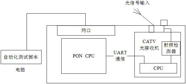
[0049] Such as figure 1 as shown, figure 1 It is a schematic structural diagram of a traditional optical receiver testing method in an optical network unit. exist figure 1 Among them, the ONU includes a PON module and a CATV optical receiver, wherein the PON module is connected to the CATV optical receiver through a Universal Asynchronous Receiver / Transmitter (UART, Universal Asynchronous Receiver / Transmitter), and the two can communicate through the UART . Here, the CATV optical receiver is an independent module, which is mainly used to watch TV...


PUM


Abstract

The invention discloses a test method, device and computer-readable storage medium of an optical receiver. Wherein, the method includes: receiving a test instruction carrying at least an identification mark, and the identification mark is associated with the optical receiver to be tested; generating a level reading instruction based on the test order; sending a message to the optical receiver to be tested Sending the level reading instruction; receiving the output level sent by the optical receiver under test; the output level is obtained by the optical receiver under test based on the level reading instruction; based on the The output level judges whether the optical receiver to be tested is qualified.

Description

technical field [0001] The invention relates to the technical field of automatic testing of digital communication products, in particular to a testing method, device and computer storage medium of an optical receiver. Background technique [0002] In the field of optical network communication, an optical network unit (ONU, Optical Network Unit) includes a passive optical network (PON, Passive Optical Network) module and a cable television (CATV) optical receiver, wherein, for the optical receiver set in the optical network unit The qualification test of the machine often adopts the traditional manual test method, specifically: first, manually connect the optical receiver in the optical network unit and the test instrument, and judge the output of the optical receiver by manually checking the Pass and Fail displayed on the test instrument. Whether the level of the optical network unit is qualified, and then judge whether the optical receiver is qualified. With this test metho...

Claims


Application Information

Patent Timeline
Patent Type & Authority Patents(China)
IPC IPC(8): H04B10/077
CPCH04B10/0779
Inventor 吕红奎李绍杰郭雷杜军
Owner WUHAN YANGTZE OPTICAL TECH
Why Eureka
Try Eureka