
Air-blowing connector

A connector and air blowing technology, applied in the field of optical fiber, can solve the problems of poor product stability and looseness, and achieve the effect of improving the firmness and stability, easy assembly and high efficiency

Pending Publication Date: 2021-05-28
惠州市飞博康实业有限公司
View PDF1 Cites 0 Cited by
  • Summary
  • Abstract
  • Description
  • Claims
  • Application Information

AI Technical Summary

Problems solved by technology

[0002] In the prior art, the outer shell of the connector is divided into two parts to assemble and fix, and basically the two parts are fixed to each other, so that the connector becomes a whole. For example, the patent number is: CN 103576246 B A fiber optic connector is proposed, in which its first housing and second housing are directly fixed to each other through the points in the two. Such an assembly and fixing method is prone to the following problems when used, that is, when the first housing After the body is loose, the second shell will also loosen, resulting in poor firmness and stability of the assembled product

Method used


Image

  • Air-blowing connector
  • Air-blowing connector
  • Air-blowing connector

Examples


Embodiment Construction

[0024] Embodiments of the present invention will be described below in conjunction with the accompanying drawings and related examples. In the following embodiments, and the present invention relates to relevant necessary components in the technical field, they should be regarded as known technologies in the technical field, which are known and mastered by those skilled in the technical field.

[0025] In describing the present invention, it should be understood that the terms "transverse", "upper", "lower", "front", "rear", "left", "right", "vertical", "horizontal", The orientation or positional relationship indicated by "inside" is based on the orientation or positional relationship shown in the drawings, which is only for the purpose of describing the present invention and simplifying the description, rather than indicating or implying that the referred device or element must have a specific orientation , are constructed and operated in a specific orientation, and therefore...


PUM


Abstract

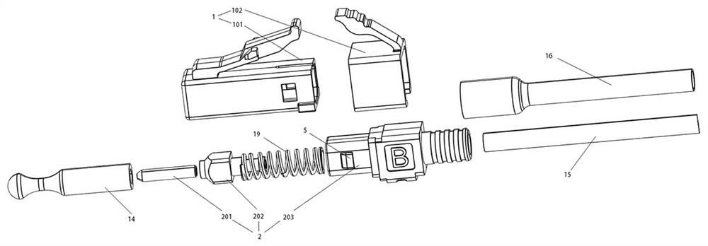
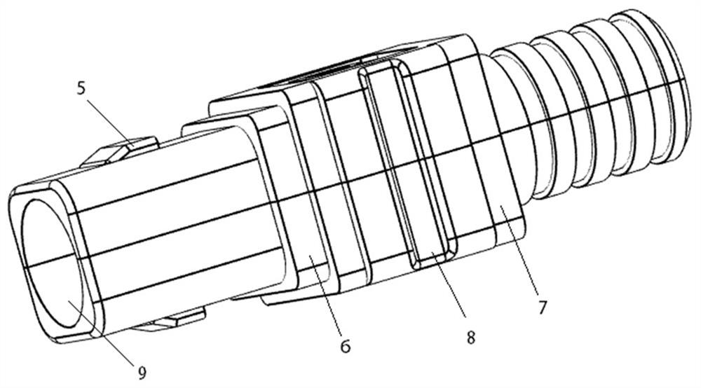
The invention relates to the technical field of optical fibers, and particularly discloses an air-blowing connector which comprises a frame sleeve and an insertion core assembly fixed in the frame sleeve, the frame sleeve comprises a front frame sleeve and a rear frame sleeve connected with the end of the front frame sleeve, the insertion core assembly comprises an insertion core, a tail handle and a clamping piece, and the two ends of the tail handle are connected with the insertion core and the clamping piece respectively. The clamping piece is formed by buckling a clamping piece A and a clamping piece B. The face, buckled with each other, of the clamping piece A and the face, buckled with each other, of the clamping piece B are provided with a pair of buckling grooves and a pair of buckling pieces respectively, the side face of the clamping piece A and the side face of the clamping piece B are provided with buckles respectively, and the middle of the clamping piece is provided with a U-shaped arc face and a fixing plane. The number of used accessories is smaller, the assembling efficiency is higher, and part assembling is firmer and more stable.

Description

technical field [0001] The invention relates to the field of optical fiber technology, in particular to an air blowing connector. Background technique [0002] In the prior art, the outer shell of the connector is divided into two parts to assemble and fix, and basically the two parts are fixed to each other, so that the connector becomes a whole. For example, the patent number is: CN 103576246 B A fiber optic connector is proposed, in which its first housing and second housing are directly fixed to each other through the points in the two, such an assembly and fixing method is prone to the following problems when used, that is, when the first housing After the first body is loose, the second housing will also loosen, resulting in poor firmness and stability of the assembled product. Contents of the invention [0003] Aiming at the technical defects existing in the background technology, the present invention proposes an air blowing connector, which solves the above techn...

Claims


Application Information

Patent Timeline
IPC IPC(8): G02B6/38
CPCG02B6/3807G02B6/389G02B6/52G02B6/3821G02B6/3849G02B6/387G02B6/3837
Inventor 李尧乐
Owner 惠州市飞博康实业有限公司
Learn More