
Landing gear wheel rotation angle measuring device

A technology of angle measurement and landing gear, applied in the direction of angle/taper measurement, etc., can solve the problems of flight accidents, the front wheel of the aircraft is not completely straightened, etc.

Inactive Publication Date: 2021-05-28
COMAC +1
View PDF5 Cites 0 Cited by
  • Summary
  • Abstract
  • Description
  • Claims
  • Application Information

AI Technical Summary

Problems solved by technology

However, if the front wheel of the aircraft is not properly aligned due to improper assembly of the front wheel or equipment aging, etc., the front wheel of the aircraft is not completely aligned when the turning handwheel is adjusted; once this happens, a flight accident is very likely to occur

Method used


Image

  • Landing gear wheel rotation angle measuring device
  • Landing gear wheel rotation angle measuring device
  • Landing gear wheel rotation angle measuring device

Examples


Embodiment 1

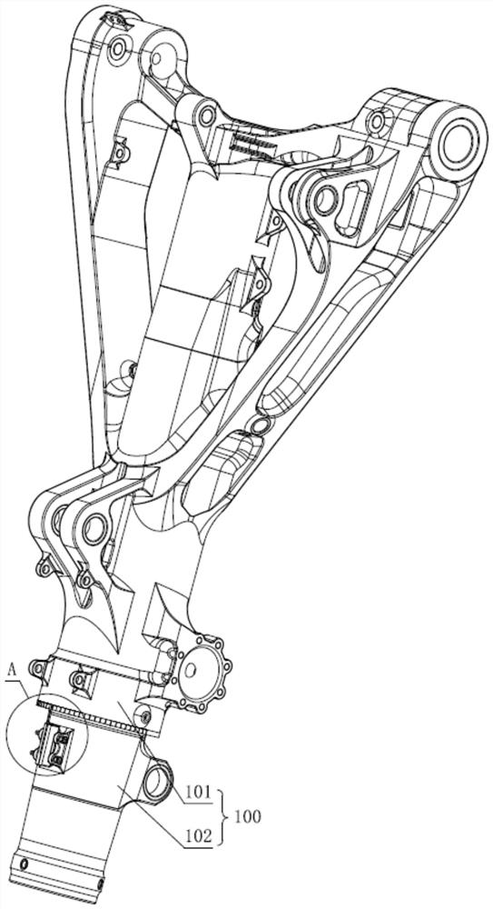
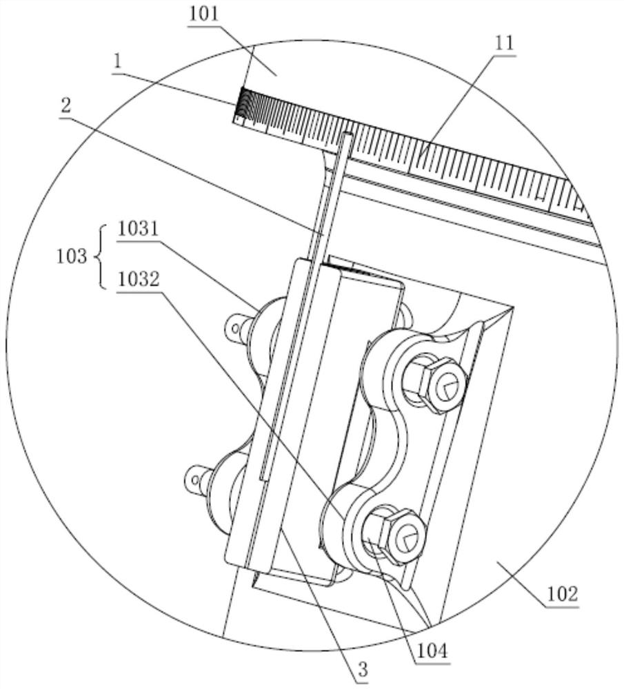
[0037] see figure 1 and figure 2 , the present embodiment provides a landing gear wheel rotation angle measuring device for measuring the rotation angle of the rotating cylinder assembly 100 in the landing gear. The rotating cylinder assembly 100 includes an outer cylinder 101 and an inner cylinder 102 connected in rotation with the outer cylinder 101. Connected to the fuselage of the aircraft, the inner cylinder 102 is connected to the wheels of the aircraft. The landing gear in the present embodiment is the front landing gear of the aircraft, and the wheels on the landing gear are the front wheels of the aircraft.

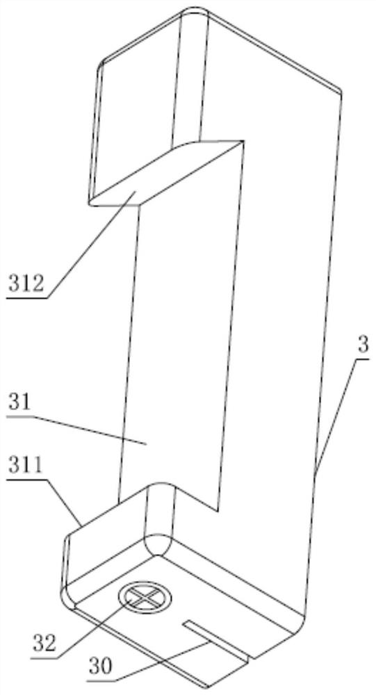
[0038] still see figure 1 and figure 2 , the landing gear wheel angle measuring device includes: a scale 1, which is wound on the outer cylinder 101; a pointer 2, which is used to indicate the scale marks 11 on the scale 1, and is detachably installed on the inner cylinder 102; The base 3 has a slot 31 , and the inner cylinder 102 is provided with a protrus...

Embodiment 2

[0050] This embodiment provides another landing gear wheel angle measuring device, see Figure 8 and Figure 9 , the landing gear wheel angle measuring device is basically the same as the landing gear wheel angle measuring device in Embodiment 1, the difference is that:

[0051] One end of the scale 1 is connected to the other end of the scale 1 through a tension spring 12; both ends of the scale 1 are provided with a second mounting hole 112; The other end of the spring 12 is hooked on the second mounting hole 112 at the other end of the scale 1 .

[0052] The assembly process of scale 1 in the present embodiment is as follows:

[0053] First wrap the strip-shaped scale 1 around the outer cylinder 101 so that the scale 1 is in a ring shape, then hook one end of the tension spring 12 to one end of the scale 1, and then stretch the tension spring 12 so that the other end of the tension spring 12 One end is hooked to the other end of the scale 1 , so that the annular scale 1 ...


PUM


Abstract

The invention relates to the technical field of aircraft debugging, and discloses a landing gear wheel rotation angle measuring device. The landing gear wheel rotation angle measuring device is used for measuring the rotation angle of a rotary drum assembly in a landing gear; the rotary drum assembly comprises an outer drum and an inner drum rotationally connected with the outer drum; the outer drum is connected to an aircraft body; the inner drum is connected to an aircraft wheel. The landing gear wheel rotation angle measuring device comprises a scale which is wound on the outer drum, and a pointer used for indicating scale marks on the scale and is detachably mounted on the inner drum. The landing gear wheel rotation angle measuring device can be arranged on a nose landing gear of an aircraft; the scale mark indicated by the pointer when the front wheel of the aircraft is straightened is observed firstly, then the scale mark indicated by the pointer when the turning hand wheel of the aircraft is straightened is observed; and the deflection angle of the front wheel of the aircraft when the turning hand wheel of the aircraft is straightened is obtained through the scale difference between the scale marks. Therefore, whether the deflection angle meets the requirement is judged. After the front wheel of the aircraft is debugged, the pointer mounted on the inner drum can be detached, so that normal flight and sliding of the aircraft are not influenced.

Description

technical field [0001] The invention relates to the technical field of aircraft debugging, in particular to a device for measuring the wheel rotation angle of a landing gear. Background technique [0002] One way to control the aircraft to turn on the ground is to manipulate the wheels on the nose landing gear of the aircraft, that is, to manipulate the nose wheels of the aircraft to deflect to make the aircraft turn. Controlling the steering of the aircraft when taxiing on the ground is generally accomplished by manipulating the steering handwheel in the aircraft cab, that is, the pilot of the aircraft manipulates the steering handwheel to adjust the deflection angle of the front wheels of the aircraft, so as to realize the steering of the aircraft. [0003] Wherein, if the aircraft needs to slide forward in a straight line, it is necessary to straighten the turning handwheel so that the front wheels of the aircraft roll forward. However, if the front wheels of the aircraf...

Claims


Application Information

Patent Timeline
Patent Type & Authority Applications(China)
IPC IPC(8): G01B5/24
CPCG01B5/24
Inventor 吴晓君袁庆超李超花磊刘飒马兰雨
Owner COMAC
Learn More