
Longitudinal whole-process automatic feeding and positioning device and method

A positioning device and full-automatic technology, applied in the direction of conveyors, mechanical conveyors, conveyor objects, etc., can solve the problems of low precision and position precision, low degree of automation, high labor intensity, etc., to achieve improved production efficiency, convenient operation, The smooth effect of the conveying process

Pending Publication Date: 2021-05-28
上海中船临港船舶装备有限公司 +1
View PDF3 Cites 0 Cited by
  • Summary
  • Abstract
  • Description
  • Claims
  • Application Information

AI Technical Summary

Problems solved by technology

However, this device does not involve how to erect the manually hoisted longitudinals. The position of the longitudinals on the positioning line is also adjusted by manually pushing the rollers, and pre-positioned by manual spot welding.
The entire longitudinal installation process still relies on manual operation, which has large errors, high labor intensity, low work efficiency and low degree of automation
[0006] To sum up, the vertical angle accuracy and position accuracy of the installation and positioning of the longitudinals in the prior art are low, and the installation relies on manual operation, which has poor safety, large errors, high labor intensity, low work efficiency, and a low degree of automation. The installation process requires manual pre-positioning of spot welding and transfer of longitudinal installation stations and welding stations.

Method used


Image

  • Longitudinal whole-process automatic feeding and positioning device and method
  • Longitudinal whole-process automatic feeding and positioning device and method
  • Longitudinal whole-process automatic feeding and positioning device and method

Examples


Embodiment Construction

[0081] The specific embodiments of the present invention will be described in detail below in conjunction with the accompanying drawings, so that those skilled in the art can more clearly understand how to practice the present invention. While the invention has been described in connection with preferred specific embodiments thereof, these embodiments are illustrative only and are not intended to limit the scope of the invention.

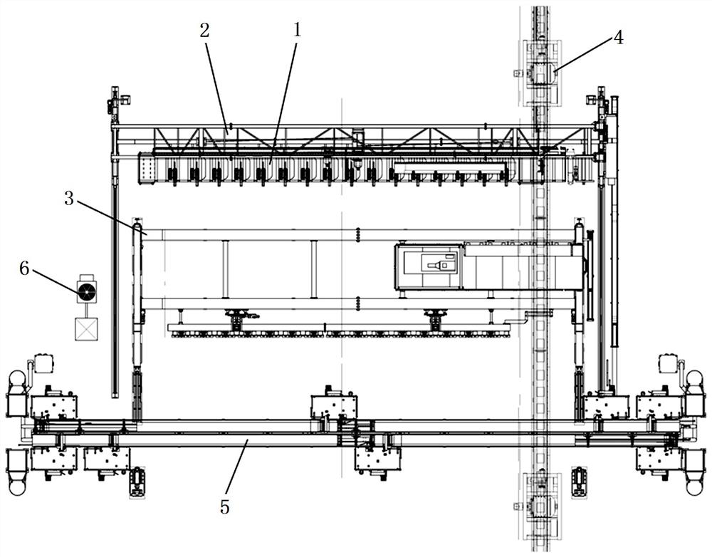
[0082] see figure 1 , a full-range automatic feeding and positioning device for longitudinals, comprising a longitudinals feeding device 1, an electromagnetic retrieving gantry 2, a longitudinals positioning trolley 3, and a segment conveying device 4 arranged in sequence along the direction of the production line.

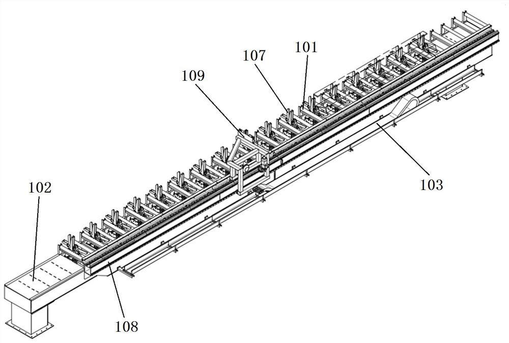
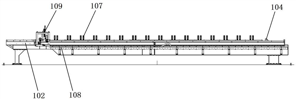
[0083] see Figure 2 to Figure 4 , The longitudinal bone feeding device 1 includes a feeding roller table, a vertical positioning device, and a longitudinal positioning device.

[0084] The feeding roller table is used to convey the l...


PUM


Abstract

The invention discloses a longitudinal whole-process automatic feeding and positioning device and method. The device comprises a longitudinal feeding device, an electromagnetic material taking portal frame, a longitudinal positioning trolley and a segment conveying device which are sequentially arranged in the direction of a production line, wherein, the longitudinal feeding device comprises a feeding roller way, a vertical positioning device and a longitudinal positioning device; the electromagnetic material taking portal frame comprises a first portal frame track, a movable portal frame, a first lifting cross beam and an electromagnetic grabbing arm with a first electromagnetic block; the longitudinal positioning trolley comprises a moving trolley track, a moving trolley, a second lifting cross beam, a second electromagnetic block, a third electromagnetic block and a positioning device; and the segment conveying device comprises a roller wheel platform, a clamping trolley track, a first clamping trolley, a second clamping trolley, a first hydraulic chuck and a second hydraulic chuck. Through combination of various conveying facilities, automatic feeding and positioning are realized in the whole process, the longitudinal installation process has the advantages of being flat in supporting, stable in movement, good in safety and convenient to operate, the production efficiency is improved, and the production cost is reduced.

Description

technical field [0001] The invention belongs to the field of ship welding, and in particular relates to a full-range automatic feeding and positioning device and method for longitudinal bones. Background technique [0002] In the hull construction process, the planar subsection production line is an important part of the hull assembly and welding facilities, and its operation mode and automation degree determine the production quality and efficiency of the hull assembly and welding. The plane segmentation production line generally includes paneling stations, marking stations, longitudinal bone installation stations, longitudinal bone welding stations, T-shaped bar installation stations, T-shaped bar welding stations, etc. For the installation station of longitudinals, its main task is to install several longitudinals at equal intervals on the positioning line of the bottom plate in a vertical standing state. The vertical angle accuracy of the web erection and the position a...

Claims


Application Information

Patent Timeline
IPC IPC(8): B65G47/92B65G35/00B65G47/22B65G13/06B65G47/88
CPCB65G47/92B65G35/00B65G47/22B65G13/06B65G47/883
Inventor 杨润党宋旭杨安海顾胜于津伟刘鹏
Owner 上海中船临港船舶装备有限公司
Learn More