
Multifunctional fish tank pneumatic filter

A filter and multi-functional technology, which is applied in the fields of filtration treatment, fish farming, chemical instruments and methods, etc., can solve the problem of failing to achieve high-efficiency filtration effect and cultivating nitrifying bacteria, dirt mixed back into the fish tank, and users Trouble and other problems, to achieve the effect of accelerating the upward flow of airflow and water flow, increasing the amount of dissolved oxygen, and enhancing the filtering effect

Pending Publication Date: 2021-05-25
黄浩奇
View PDF0 Cites 0 Cited by
  • Summary
  • Abstract
  • Description
  • Claims
  • Application Information

AI Technical Summary

Problems solved by technology

[0002] Most of the fish tank pneumatic filters currently on the market use sponge as the filter medium, and the oxygen pump is used to pump air into the inner chamber of the filter to drain the water in the inner chamber, and then the outside water enters the inner chamber from the sponge. The warehouse replenishes and repeats the cycle to form a water flow, so that the sponge can simply filter the coarser particles of impurities, but this filtering method does not achieve the high-efficiency filtration effect and the effect of cultivating nitrifying bacteria, because the dirt is directly adsorbed on the sponge If the surface of the fish tank needs to be moved or taken out for cleaning, the dirt will easily be washed and mixed back into the water of the fish tank, causing a large area of ​​pollution. The whole fish tank needs to be re-changed to achieve a clean effect. users cause a lot of trouble

Method used


Image

  • Multifunctional fish tank pneumatic filter
  • Multifunctional fish tank pneumatic filter
  • Multifunctional fish tank pneumatic filter

Examples


Embodiment Construction

[0022] The following will clearly and completely describe the technical solutions in the embodiments of the present invention with reference to the accompanying drawings in the embodiments of the present invention. Obviously, the described embodiments are only some of the embodiments of the present invention, not all of them. Based on the embodiments of the present invention, all other embodiments obtained by persons of ordinary skill in the art without making creative efforts belong to the protection scope of the present invention.

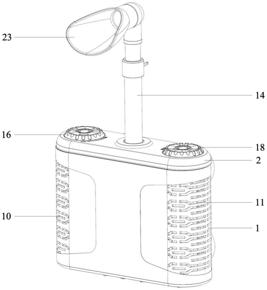
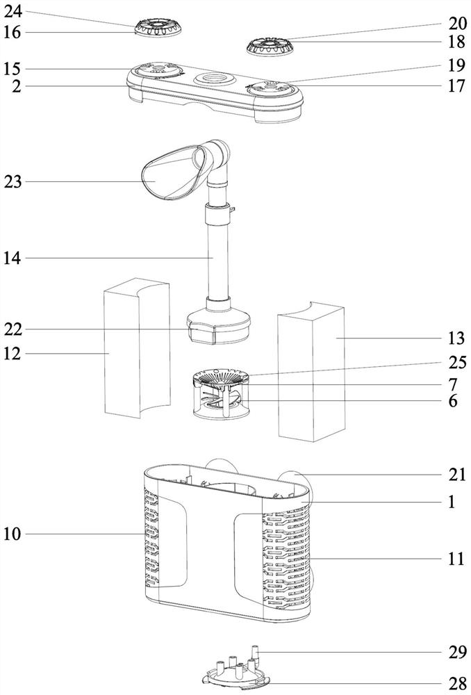
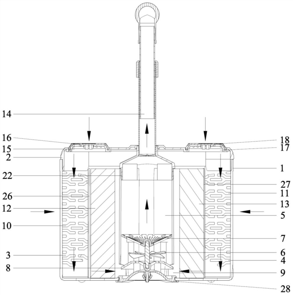
[0023] Such as Figure 1 to Figure 4 A kind of multi-functional fish tank pneumatic filter of the present invention as shown, comprises filter casing 1, and the top cover of filter casing 1 is provided with a top cover 2, and the left and right sides of filter casing 1 interior are respectively provided with left rubbish collection bin 3 and The right garbage collection bin 4 and the inner middle side of the filter housing 1 are provided with a c...


PUM


Abstract

The invention discloses a multifunctional fish tank pneumatic filter. The multifunctional fish tank pneumatic filter comprises a filter shell, the top of the filter shell is provided with a top cover in a covered mode, the left side and the right side of the interior of the filter shell are provided with a left garbage collecting bin and a right garbage collecting bin respectively, the middle side of the interior of the filter shell is provided with a bacterium cultivation bin, an impeller for driving water to flow upwards is installed at the bottom of the bacterium cultivation bin, a left through hole and a right through hole which communicate with the left garbage collecting bin and the right garbage collecting bin are formed in the left side and the right side of the bottom of the bacterium cultivation bin respectively, a plurality of left water inlet through holes are evenly distributed in the left side of the left garbage collecting bin, a plurality of right water inlet through holes are evenly distributed in the right side of the right garbage collecting bin, left filter cotton is installed on the right side of the left garbage collecting bin, right filter cotton is installed on the left side of the right garbage collecting bin, and a water outlet pipe communicating with the bacterium cultivation bin is installed on the top cover. The multifunctional fish tank pneumatic filter is good in filtering effect, convenient to clean and capable of effectively keeping ecological balance of water quality in a fish tank.

Description

technical field [0001] The invention relates to the technical field of fish tank filters, in particular to a multifunctional fish tank pneumatic filter. Background technique [0002] Most of the fish tank pneumatic filters currently on the market use sponge as the filter medium, and the oxygen pump is used to pump air into the inner chamber of the filter to drain the water in the inner chamber, and then the outside water enters the inner chamber from the sponge. The warehouse replenishes and repeats the cycle to form a water flow, so that the sponge can simply filter the coarser particles of impurities, but this filtering method does not achieve the high-efficiency filtration effect and the effect of cultivating nitrifying bacteria, because the dirt is directly adsorbed on the sponge If the surface of the fish tank needs to be moved or taken out for cleaning, the dirt will easily be washed and mixed back into the water of the fish tank, causing a large area of ​​pollution. T...

Claims


Application Information

Patent Timeline
Patent Type & Authority Applications(China)
IPC IPC(8): A01K63/04C02F9/14
CPCA01K63/045C02F3/34C02F1/001C02F2203/006C02F2303/14
Inventor 黄浩奇
Owner 黄浩奇
Learn More