


Quick Research
Generate reliable direction feasibility study reports for your R&D in just a few steps.

Technical Q&A
Discover and master advanced knowledge NOW. Basics, ideas, possibilities, all at once.

Find Solutions
As an expert in R&D theories, this can generate solutions to your technical problems instantly.

Evaluate Feasibility
Analyze your overall solution with one click, know your potential R&D risks in advance.

Monitor Landscape
Get weekly tech updates, stay abreast of the latest tech innovations and key insights.
Fabricated bridge
A prefabricated and bridge technology, applied in the direction of bridges, bridge construction, bridge forms, etc., can solve the problems of large size and weight, inconvenient assembly and transportation, and poor load-bearing capacity of straight bridges
- Summary
- Abstract
- Description
- Claims
- Application Information
AI Technical Summary
Problems solved by technology
Method used
Image

Examples
Embodiment 1
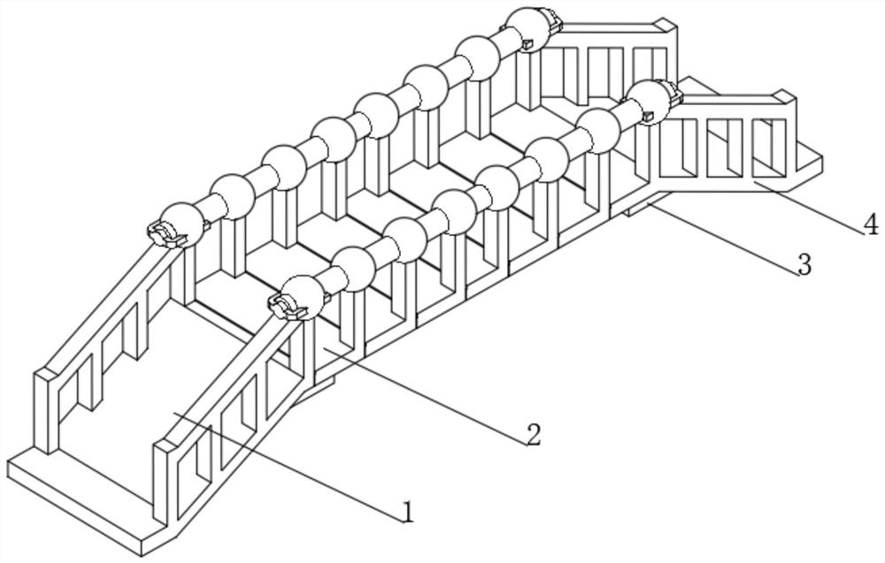
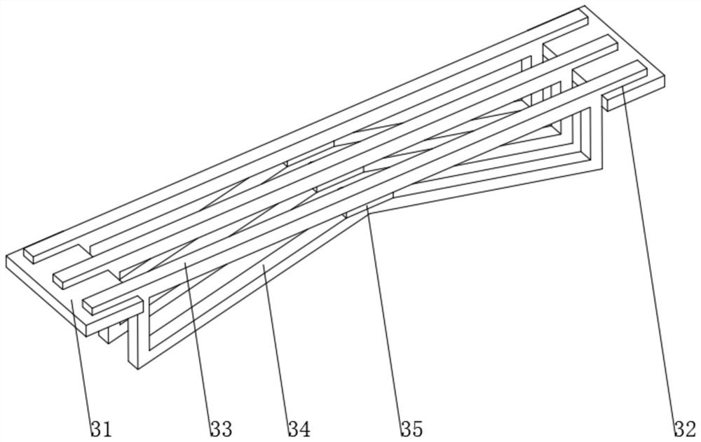
[0033] see Figure 1-3 , the present invention provides a technical solution: an assembled bridge, including a first bridge base 1, one end of the first bridge base 1 is fixedly connected with a split device 2, and one end of the first bridge base 1 is located at the bottom part of the split device 2 The support device 3 is fixedly connected, and the top of the support device 3 away from the first bridge seat 1 is fixedly connected with the second bridge seat 4. The support device 3 includes a first support seat 31 and a second support seat 32, the first support seat 31 and the second support seat 32. The top of the second support base 32 is provided with a mounting device 32, the inner wall of the mounting device 32 is slidingly connected with a cross strut 33, and the bottom of both ends of the cross strut 33 is fixedly connected with a triangular reinforcing rod 34, and the triangular reinforcing rod 34 is far away from the cross strut 33 One end is fixedly connected with a...
Embodiment 2
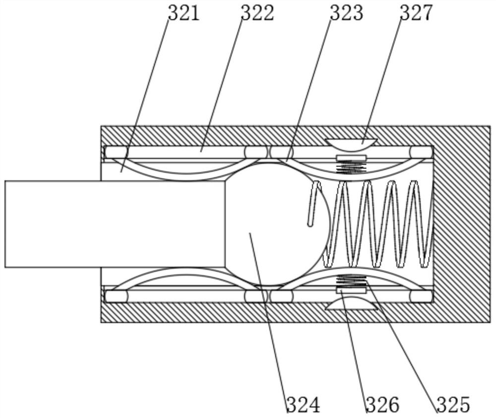
[0036] see Figure 1-6 On the basis of Embodiment 1, the present invention provides a technical solution: the split device 2 includes a bridge plate 21, the tops of both ends of the bridge plate 21 are fixedly connected with top posts 22, and the tops of the top posts 22 are fixedly connected with connecting balls 23, One side of the connecting ball 23 runs through and is slidably connected with a connecting support rod 24, and one end of the connecting supporting rod 24 is provided with a fixing groove 25, and the top and bottom of the inner wall of the fixing groove 25 are provided with barb grooves 26, and the inner wall of the fixing groove 25 is slidably connected with a fixing device 27. The fixing device 27 includes a fixed disk 271, one side of the fixed disk 271 is fixedly connected with a guide column 272, and both ends of the fixed disk 271 are fixedly connected with auxiliary inserting rods 273, and the top and bottom of the guide column 272 are provided with a rota...
PUM
 Abstract
Description
Claims
Application Information
 - R&D Engineer
- R&D Manager
- IP Professional
- Industry Leading Data Capabilities
- Powerful AI technology
- Patent DNA Extraction
Browse by: Latest US Patents, China's latest patents, Technical Efficacy Thesaurus, Application Domain, Technology Topic, Popular Technical Reports.
© 2024 PatSnap. All rights reserved.Legal|Privacy policy|Modern Slavery Act Transparency Statement|Sitemap|About US| Contact US: help@patsnap.com