
Patsnap Eureka
For R&D, Patsnap Eureka makes reading and utilizing patents & technical documents easy.
Patsnap Eureka AIR
Designed for self-driven R&D workflows. Generate viable solutions, solve complex R&D challenges, empower your innovation with AI.

Patsnap Eureka Materials
Designed for material experts only. Revolutionize your material R&D, from search, analyze, to developing new materials.

TechResearch
Generate reliable direction feasibility study reports for your R&D in just a few steps.

TechSeek
Discover and master advanced knowledge NOW. Basics, ideas, possibilities, all at once.

TechMind
As an expert in R&D Theories, TechMind can generates customized viable solutions instantly.

TechRisk
Analyze your overall solution with one click, know your potential R&D risks in advance.

TechMonitor
Get weekly tech updates, stay abreast of the latest tech innovations and key insights.
Drilling machine rotating speed monitoring system, control method and application method
A speed detection and speed technology, which is applied to the automatic control system of drilling, drilling measurement, drilling equipment, etc., can solve the problem that the speed accuracy is difficult to determine
- Summary
- Abstract
- Description
- Claims
- Application Information
AI Technical Summary
Problems solved by technology
Method used
Image

Examples
Embodiment 1
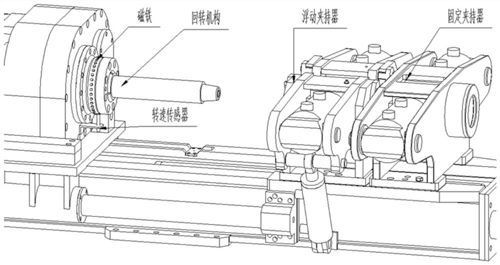
[0020] Such as figure 1 For the content shown, this embodiment will clearly and completely describe the technical solution, and the described embodiments are only some embodiments of the present invention, not all embodiments. This embodiment discloses a drilling rig speed monitoring system, which mainly includes:
[0021] The rotary mechanism, the rotary mechanism includes a rotary disk, and N magnets are arranged on the rotary disk, preferably N=72 in this embodiment, that is, 72 magnets are evenly distributed on the rotary disk of the rotary mechanism.
[0022] The rotational speed sensor includes a bracket and a sensor body, the bracket is vertically arranged at the bottom of the rotary mechanism, the sensor body is vertically arranged on the bracket, and its top is opposite to the magnet of the rotary disk.
[0023] A rotational speed threshold is set inside the processor for controlling the rotational speed of the slewing mechanism.
[0024] The gripper assembly includ...
Embodiment 2
[0028] Such as figure 1 For the content shown, this embodiment will clearly and completely describe the technical solution, and the described embodiments are only some embodiments of the present invention, not all embodiments. This embodiment discloses a method for controlling the rotational speed of a drilling rig, which mainly includes:
[0029] 72 magnets are installed on the rotary plate of the rotary mechanism, and a speed sensor is installed on the chassis, so that the sensor can detect the signal of the magnet;
[0030] When the slewing mechanism rotates, the time difference t of every two magnet signals is recorded by the speed sensor N , each time difference t N The rotation angle is 5°, and the time for the slewing mechanism to rotate one circle is N time differences t N Sum The processor calculates that the real-time rotational speed w of the slewing mechanism is divided by The processor simultaneously records the time difference t between adjacent laps x , ...
Embodiment 3
[0039] Such as figure 1 For the content shown, this embodiment will clearly and completely describe the technical solution, and the described embodiments are only some embodiments of the present invention, not all embodiments. This embodiment discloses a drilling rig speed application method, which mainly includes:
[0040] 72 magnets are installed on the rotary plate of the rotary mechanism, and a speed sensor is installed on the chassis, so that the sensor can detect the signal of the magnet;
[0041] When the slewing mechanism rotates, the time difference t of every two magnet signals is recorded by the speed sensor N , each time difference t N The rotation angle of the double gripper is 5°; the processor controls the fixed gripper to perform the clamping operation, releases the floating gripper and reverses the slewing mechanism, the rotation fixed angle of the floating gripper in the double gripper is 20°, and the drill pipe The minimum reverse angle for loosening the ...
PUM
 Abstract
Description
Claims
Application Information
 - R&D Engineer
- R&D Manager
- IP Professional
- Industry Leading Data Capabilities
- Powerful AI technology
- Patent DNA Extraction
Browse by: Latest US Patents, China's latest patents, Technical Efficacy Thesaurus, Application Domain, Technology Topic, Popular Technical Reports.
© 2024 PatSnap. All rights reserved.Legal|Privacy policy|Modern Slavery Act Transparency Statement|Sitemap|About US| Contact US: help@patsnap.com