
Vacuum extraction equipment for ironing areas

An area and equipment technology, applied in the direction of vacuum cleaners, cleaning equipment, applications, etc., can solve problems such as difficult installation and large volume of vacuum equipment

Active Publication Date: 2022-03-01
XINXING DUCTILE IRON PIPES CO LTD
View PDF0 Cites 0 Cited by
  • Summary
  • Abstract
  • Description
  • Claims
  • Application Information

AI Technical Summary

Problems solved by technology

[0003] The purpose of the present invention is to provide a dust suction device for the iron mixing area, aiming to solve the problem that the existing dust suction devices are generally large in size and difficult to install

Method used


Image

  • Vacuum extraction equipment for ironing areas
  • Vacuum extraction equipment for ironing areas
  • Vacuum extraction equipment for ironing areas

Examples


Embodiment Construction

[0022] In order to make the technical problems, technical solutions and beneficial effects to be solved by the present invention clearer, the present invention will be further described in detail below in conjunction with the accompanying drawings and embodiments. It should be understood that the specific embodiments described here are only used to explain the present invention, not to limit the present invention.

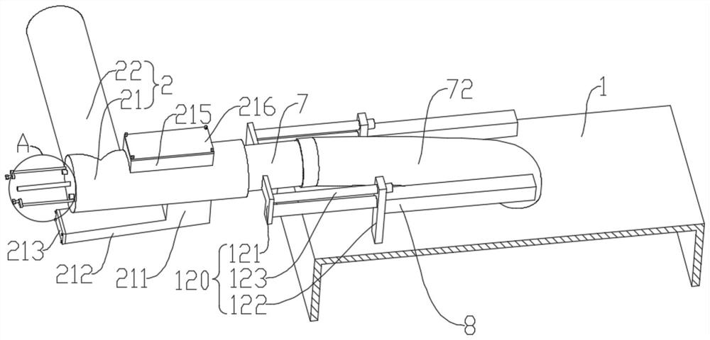
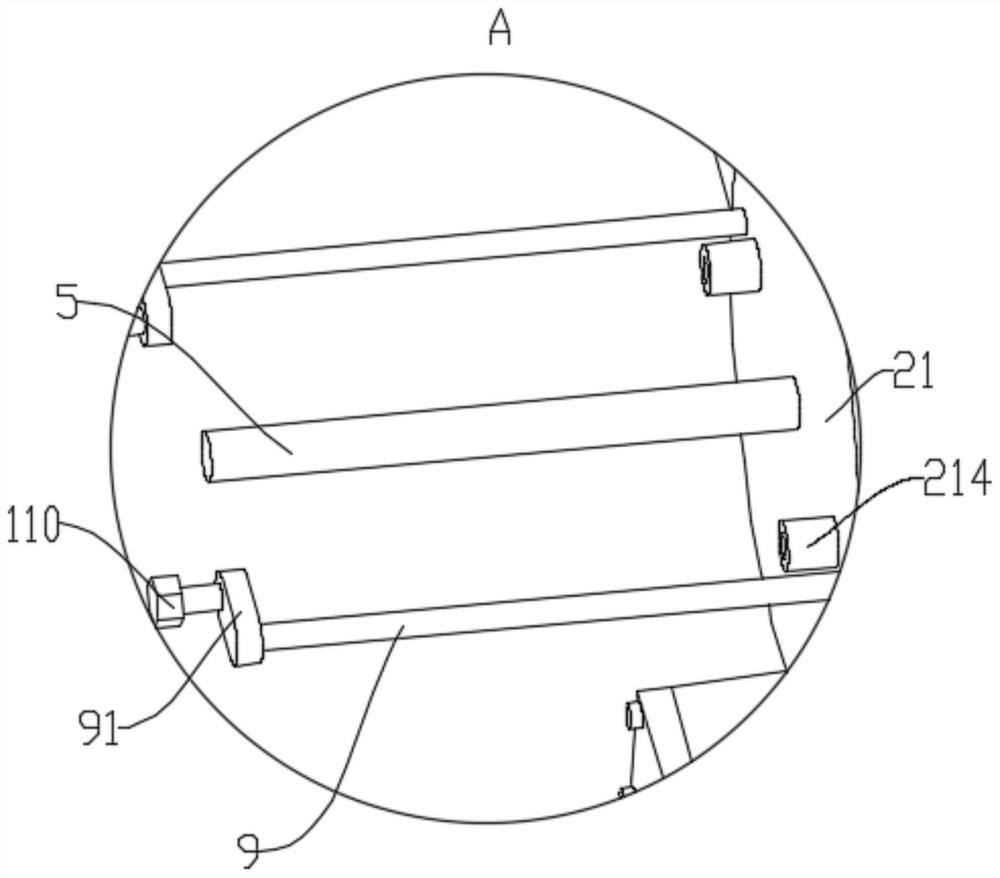
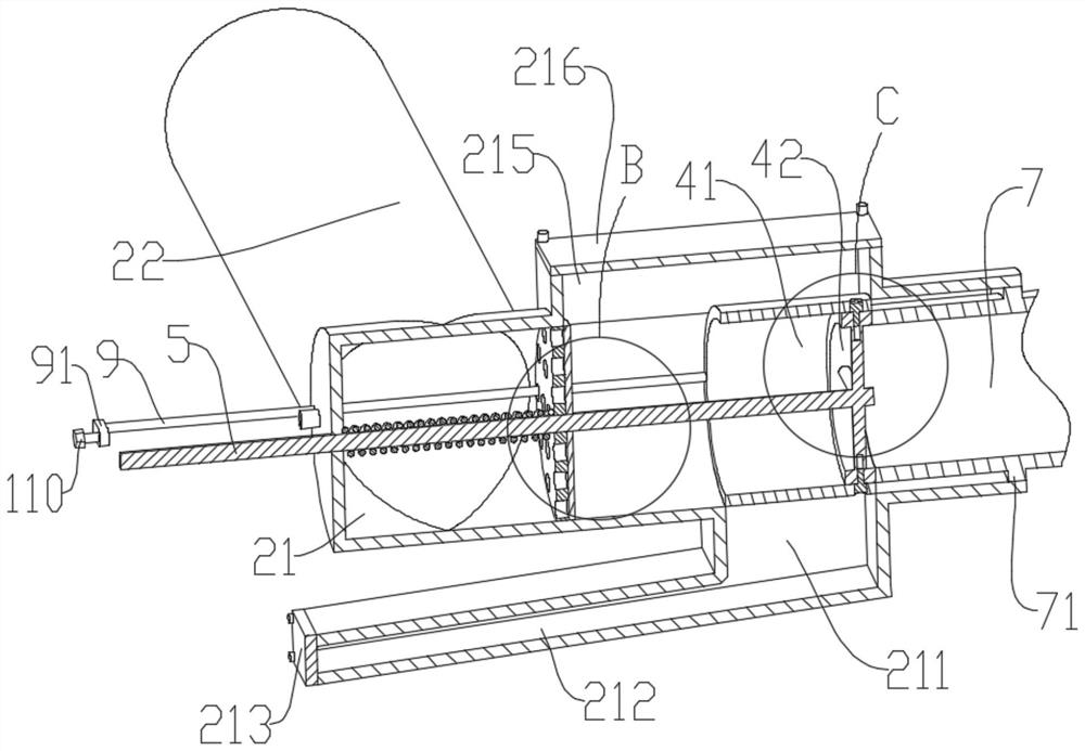
[0023] Please also refer to Figure 1 to Figure 5 Now, the dust collection equipment for ironing area provided by the present invention will be described. The dust suction equipment used in the iron mixing area includes a dust suction cover 1, a docking pipeline 2, a filter assembly 3, a positioning pipe 4, a connecting shaft 5, a compression spring 6, a moving pipe 7 and a telescopic assembly 8. The bottom end of the dust suction cover body 1 is an open end. The butt joint pipeline 2 is relatively fixed with the vacuum cover 1, and is in an L-shaped structure, i...


PUM


Abstract

The invention provides a dust collection device for the iron mixing area, which belongs to the technical field of dust collection devices, and includes a dust collection cover, a docking pipeline, a filter assembly, a positioning pipe, a connecting shaft, a compression spring, a moving pipe and a telescopic assembly . The butt joint pipeline includes a horizontal section and a connection section connected to the horizontal section. The filter assembly slides through the horizontal section. The positioning pipe coaxially slides through the horizontal section. The middle part of the connecting shaft penetrates the filter assembly and is fixedly connected with the filter assembly, one end is fixedly connected with the positioning pipe, and the other end slides through the closed end of the horizontal section. The compression spring is sheathed on the connecting shaft. The moving pipe communicates with the dust suction cover through the telescopic tube and is slidably connected with the dust suction cover through the connection assembly. The telescopic assembly is connected with the dust suction cover body. The dust suction equipment used in the iron mixing area provided by the present invention is installed separately, avoiding the problem that the existing dust suction equipment generally has a large volume and is relatively difficult to install.

Description

technical field [0001] The invention belongs to the technical field of dust-absorbing equipment, and more specifically relates to a dust-absorbing equipment used in an iron mixing area. Background technique [0002] The current iron mixing method generally uses the crane to lift the molten iron ladle to the corresponding electric furnace for iron mixing, and a large amount of smoke and dust will be generated during the iron mixing. In order to meet the requirements of environmental protection, it is necessary to install dust collection equipment above the iron mixing area. However, the existing vacuum equipment is generally bulky and difficult to install. Contents of the invention [0003] The object of the present invention is to provide a dust suction device for the iron mixing area, aiming to solve the problem that the existing dust suction devices are generally large in size and difficult to install. [0004] In order to achieve the above object, the technical solutio...

Claims


Application Information

Patent Timeline
Patent Type & Authority Patents(China)
IPC IPC(8): A47L5/12A47L9/00A47L9/02A47L9/10
CPCA47L5/12A47L9/00A47L9/02A47L9/10
Inventor 陈江涛陈建波王昌辉李晓东孙宏董平李志杰
Owner XINXING DUCTILE IRON PIPES CO LTD
Learn More