
Pay-off device for many groups of cable reels

A pay-off device and cable reel technology, which is applied in the directions of transportation and packaging, delivery of filamentous materials, thin material processing, etc., can solve problems such as difficult tension, long time consumption, and large work space occupation

Active Publication Date: 2021-05-07
白银有色长通电线电缆有限责任公司 +1
View PDF20 Cites 0 Cited by
  • Summary
  • Abstract
  • Description
  • Claims
  • Application Information

AI Technical Summary

Problems solved by technology

[0002] Due to the complicated specifications of cables, during the cable production and manufacturing process, many groups of cable reels will be required to be paid out at the same time. For example, the single wire in the center layer of the conductor core is twisted instead of twisted, and multiple insulated wire cores in parallel wires are paid out synchronously. Regardless of whether it is conductor core stranding or extrusion equipment, generally only one central pay-off frame is installed. In the case of simultaneous release of multiple sets of cable reels, usually only multiple sets of simple mobile pay-off frames can be used, which takes up a lot of space. The work site brings a lot of inconvenience to the production
The simple pay-off rack is labor-intensive and time-consuming during the loading and unloading process, and the tension is difficult or impossible to adjust, resulting in unstable pay-off tension, low labor efficiency, and difficult product quality assurance

Method used


Image

  • Pay-off device for many groups of cable reels
  • Pay-off device for many groups of cable reels
  • Pay-off device for many groups of cable reels

Examples


Embodiment 1

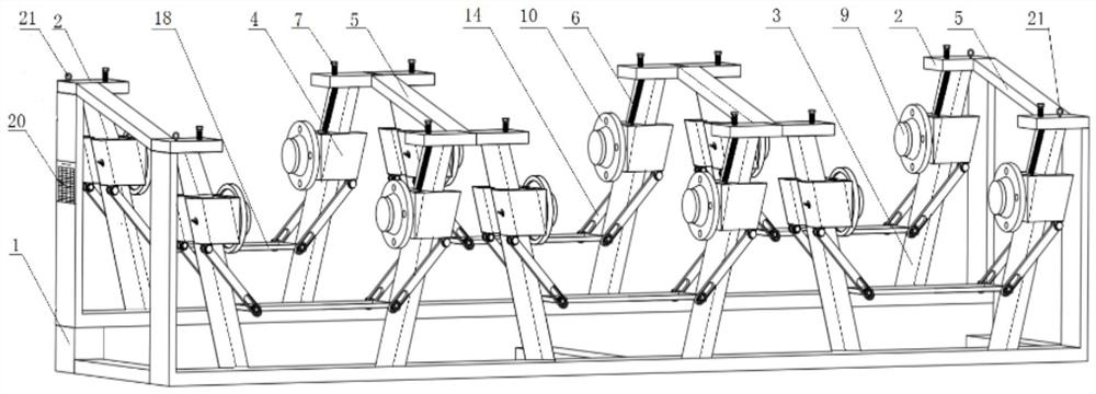
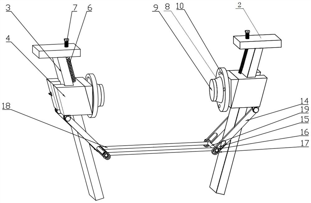
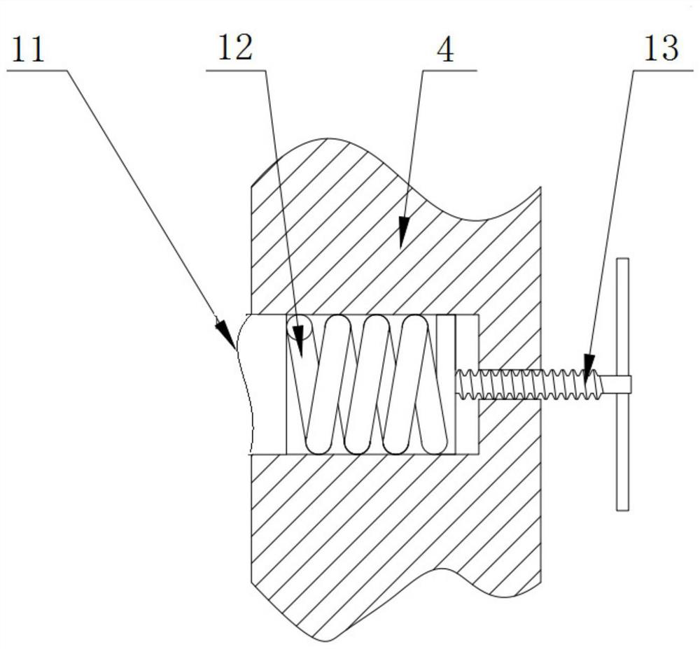
[0021] A multi-group cable reel pay-off device, such as Figures 1 to 3 , including a frame 1, the frame 1 is provided with two front and rear discharge wire frame groups along the length direction, each discharge wire frame group is composed of a number of wire release frame bodies connected in series, and the wire discharge frame body includes two inverted Trapezoidally arranged on the guide rail 3 on the frame 1, the top of the guide rail 3 is provided with a fixed plate 2, a slider 4 is slidably arranged on the guide rail 3, and a thimble shaft 8 and a thimble head are coaxially arranged on the inner side of the slider 4 9. The tension disc 10, the upper end of the slider 4 is connected to the fixed plate 2 through the tension spring 6, two pull rods 14 are hinged on both sides of the upper guide rail 3 on the lower side of the slider 4, and the two guide rails 3 of a pay-off frame body A bracket 18 is hinged between the upper pull rods 14, and the bracket 18 and the pull ...

Embodiment 2

[0033] On the basis of Embodiment 1, the rear discharge wire frame group set on the frame 1 is overall higher than the front discharge wire frame group. While facilitating the lead-out of the rear row of wires, it avoids winding of the lead-out wires from the front and rear disks.

Embodiment 3

[0035]On the basis of Embodiment 1, a connecting plate 5 is connected between the rear discharge wire frame body and the fixed plate 2 of the front discharge wire frame body arranged on the frame 1 along the front and rear direction. The connecting plate 5 connects the front and rear two discharge wire frame bodies together, making it stable in structure and safe and reliable in use.


PUM


Abstract

The invention discloses a pay-off device for many groups of cable reels, and belongs to the field of wire and cable production equipment. The pay-off device for many groups of cable reels comprises a rack, wherein a front row of pay-off rack group and a rear row of pay-off rack group are arranged on the rack in the length direction, each row of pay-off rack group is formed by connecting a plurality of pay-off rack bodies in series, each pay-off rack body comprises two guide rails which are arranged on the rack in an inverted trapezoidal mode, a fixing plate is arranged on the tops of the guide rails, and sliding blocks are arranged on the guide rails in a sliding mode; and an ejector pin shaft, an ejector pin head and a tension disc are coaxially arranged at the inner side of each sliding block, the upper end of each sliding block is connected with the fixing plate through an extension spring, two pull rods are hinged to the two sides of the upper guide rail at the lower side of each sliding block, and a bracket is hinged between the pull rods on the two guide rails of one pay-off rack body. The pay-off device for many groups of cable reels is capable of realizing stable pay-off for many cable reels of different specifications at the same time, convenient in coil loading and unloading, low in labor intensity, without the need of extra power input in the using process, low in using cost, high in practicability, and convenient to apply and popularize.

Description

technical field [0001] The invention belongs to the field of wire and cable production equipment, in particular to a multi-group cable reel pay-off device. Background technique [0002] Due to the complicated specifications of cables, during the cable production and manufacturing process, many groups of cable reels will be required to pay off at the same time. For example, the single wire in the center layer of the conductor core is twisted instead of twisted, and multiple insulated cores in parallel lines are paid out synchronously. Regardless of whether it is conductor core stranding or extrusion equipment, generally only one central pay-off frame is installed. In the case of simultaneous release of multiple sets of cable reels, usually only multiple sets of simple mobile pay-off frames can be used, which takes up a lot of space. The work site brings a lot of inconvenience to the production. The simple pay-off rack is labor-intensive and time-consuming during the loading ...

Claims


Application Information

Patent Timeline
IPC IPC(8): B65H49/32B65H49/36B65H67/02B65H59/04
CPCB65H49/324B65H49/36B65H67/02B65H59/04B65H2701/34
Inventor 魏永昌项冰仑李伟田伟星
Owner 白银有色长通电线电缆有限责任公司
Learn More