
Photoelectric transmission interface and corresponding photoelectric transmission line and photoelectric bayonet socket

A technology of optoelectronic transmission and electrical interface, applied in the field of optoelectronic transmission, can solve problems such as inconvenient use, and achieve the effect of positive and negative plugging and convenient use.

Active Publication Date: 2021-05-04
南京芯欣德科技有限公司
View PDF3 Cites 0 Cited by
  • Summary
  • Abstract
  • Description
  • Claims
  • Application Information

AI Technical Summary

Problems solved by technology

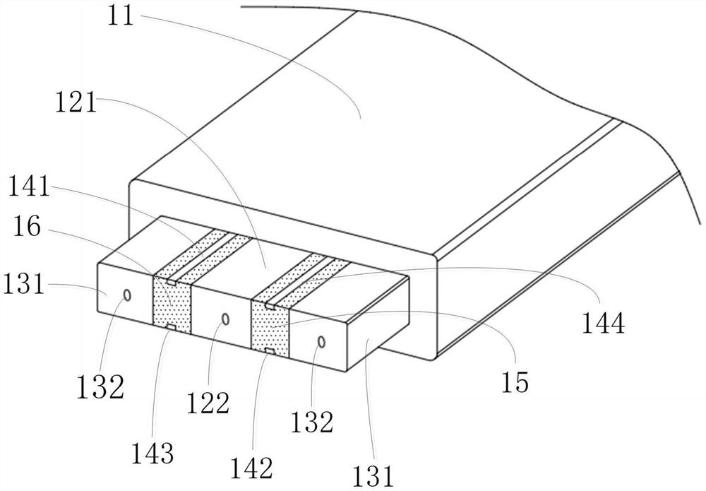
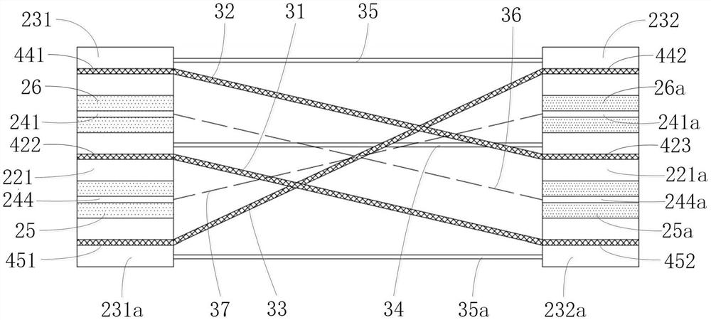
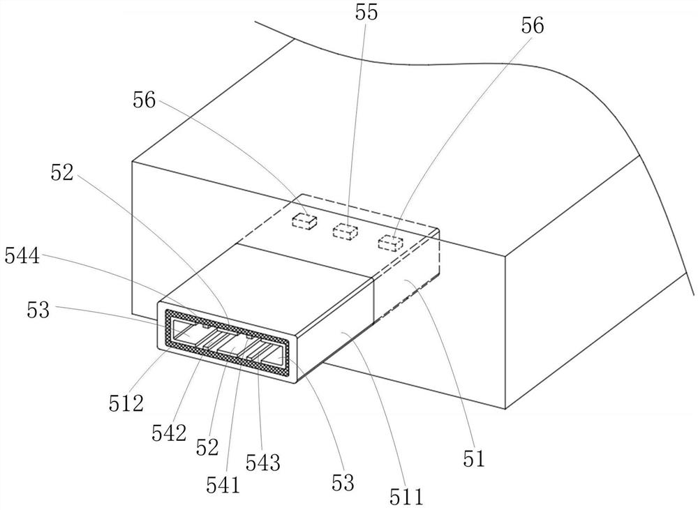
[0004] The invention provides a photoelectric transmission interface, a corresponding photoelectric transmission line, and a photoelectric socket. The photoelectric transmission interface arranges the middle optical fiber body in the middle optical fiber fixing column, and arranges the lateral optical fiber body in the lateral optical fiber fixing column, so that the optical fiber The interface and the electrical interface are fused together to solve the problem that the photoelectric hybrid cable formed by packaging the optical cable and the cable together in the prior art is very inconvenient to use

Method used


Image

  • Photoelectric transmission interface and corresponding photoelectric transmission line and photoelectric bayonet socket
  • Photoelectric transmission interface and corresponding photoelectric transmission line and photoelectric bayonet socket
  • Photoelectric transmission interface and corresponding photoelectric transmission line and photoelectric bayonet socket

Examples


Embodiment Construction

[0053] The following will clearly and completely describe the technical solutions in the embodiments of the present invention with reference to the accompanying drawings in the embodiments of the present invention. Obviously, the described embodiments are only some, not all, embodiments of the present invention. Based on the embodiments of the present invention, all other embodiments obtained by those skilled in the art without making creative efforts belong to the protection scope of the present invention.

[0054] Directional terms mentioned in the present invention, such as "up", "down", "front", "back", "left", "right", "inside", "outside", "side", "top" Words such as "bottom" and "bottom" only refer to the orientation of the drawings, and the directional terms used are used to illustrate and understand the present invention, but not to limit the present invention.

[0055] Words such as "first" and "second" in the terminology of the present invention are only used for des...


PUM


Abstract

The invention provides a photoelectric transmission interface. The photoelectric transmission interface comprises a body, a middle optical interface, lateral optical interfaces, a first insulating part and a second insulating part; the middle optical interface is arranged in the middle of the body and comprises a middle optical fiber fixing column and a middle optical fiber body, the two lateral optical interfaces are arranged on the two sides of the body and comprise lateral optical fiber fixing columns and lateral optical fiber bodies, and the two lateral optical interfaces are arranged in a central symmetry mode relative to the center point of the body. The first insulating part is arranged on the body between the middle optical interface and the lateral optical interface, and the second insulating part is arranged on the body between the middle optical interface and the other lateral optical interface. According to the photoelectric transmission interface, the optical interface and the electrical interface are fused together, optical signals and electric energy can be transmitted at the same time, use is very convenient, and forward and reverse plugging can be achieved.

Description

technical field [0001] The invention relates to the field of photoelectric transmission, in particular to a photoelectric transmission interface, a corresponding photoelectric transmission line, and a photoelectric socket. Background technique [0002] In the traditional field of optical fiber communication, an optical fiber connector or optical fiber splice is a highly precise mechanical device. Usually, the optical cable itself cannot transmit electric energy at the same time, so it is difficult to realize remote power feeding of optical fiber communication equipment. In the prior art, optical cables and electric cables are packaged and laid together to form a photoelectric hybrid cable, which solves the problem that optical signals and electric energy cannot be transmitted simultaneously to a certain extent. But on the connector, the optical fiber connector and the cable transmission connector must still be designed and installed separately, which is very inconvenient to...

Claims


Application Information

Patent Timeline
IPC IPC(8): H01R13/40H01R13/502G02B6/38G02B6/42
CPCH01R13/40H01R13/502G02B6/3833G02B6/424
Inventor 陈相宁刘辅华
Owner 南京芯欣德科技有限公司
Learn More