
Electrical sounding imaging method for unfavorable geology steering investigation of deeply-buried long tunnel

A technology of electrical sounding and tunneling, applied in geophysical surveying, radio wave measuring systems, measuring devices, etc., can solve the problems of limited signal strength, complex environment, large dynamic range, etc.

Inactive Publication Date: 2021-05-04
WUHAN ENG SCI & TECH RESINST
View PDF4 Cites 0 Cited by
  • Summary
  • Abstract
  • Description
  • Claims
  • Application Information

AI Technical Summary

Problems solved by technology

[0003] At present, a new round of infrastructure construction peaks is coming, and the buried depth of road and railway tunnels is getting larger and larger. When the existing electrical instruments detect under long-distance complex geological conditions, they can only perform 2-dimensional imaging, resulting in low accuracy of detection results.
Two-dimensional imaging uses one surface imaging, for example, the measuring line is the X-axis, the measurement depth is the Z-axis, and the apparent resistivity ρ=(x, z). The environment is complex when working on site, and there are three main disadvantages: 1. Lots of interference , non-target geological noise, natural electromagnetic noise, human interference (civilian electricity shared by artificial buried objects, etc.) 2. The signal is weak, limited by the power of the on-site power supply, and the measurement signal strength is limited. 3. The dynamic range is large, and in the measurement As the measurement point and electrode change, the distance between the transceiver and the electrode changes greatly, and the measured signal changes greatly. If the signals of different magnitudes are accurately measured at a single time or on one surface, the resulting error will be large.

Method used


Image

  • Electrical sounding imaging method for unfavorable geology steering investigation of deeply-buried long tunnel

Examples


Embodiment Construction

[0017] Below in conjunction with accompanying drawing and specific embodiment the present invention is described in further detail:

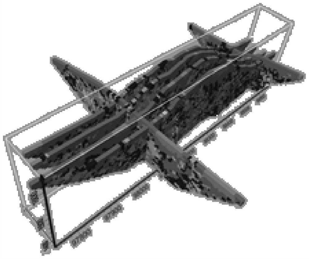
[0018] The electric depth-sounding imaging method of deep-buried long tunnel poor geological turning survey shown in the present invention, it comprises the following steps:

[0019] Step 1: Insert multiple electrodes of the electric meter into the ground of the area to be tested at equal intervals (5-10 meters) in the longitudinal direction;

[0020] Step 2: The host computer sends signal acquisition instructions to the acquisition station, and the acquisition station supplies power to each electrode of the electrical instrument, and each electrode of the electrical instrument feeds back the sensed voltage signal to the host through the acquisition station;

[0021] Step 3: The host obtains the distributed apparent resistivity data at different depths of the vertical section below the longitudinal arrangement of the electrodes of the electrical...


PUM


Abstract

The invention discloses an electrical sounding imaging method for unfavorable geology steering investigation of a deeply-buried long tunnel. The electrical sounding imaging method comprises the following steps of: 1, longitudinally inserting a plurality of electrodes of an electrical prospecting instrument into the ground of a to-be-detected area at equal intervals; 2, feeding back induced voltage signals to a host through an acquisition station by each electrode of the electrical prospecting instrument; 3, acquiring distributed apparent resistivity data of different depths of a vertical section below an electrode longitudinal arrangement position of the electrical prospecting instrument; 4, transversely inserting the plurality of electrodes of the electrical prospecting instrument into the ground of the to-be-detected area at equal intervals; 5, feeding back the induced voltage signals by each electrode of the electrical prospecting instrument to the host through the acquisition station; 6, acquiring distributed apparent resistivity data of different depths of a vertical section below an electrode transverse arrangement position of the electrical prospecting instrument; and 7, acquiring three-dimensional apparent resistivity data of different depths. According to the invention, three-dimensional electrical sounding imaging of a geological structure can be realized, and the detection accuracy is improved.

Description

technical field [0001] The invention relates to the technical field of tunnel geological detection equipment, in particular to an electrical depth-sounding imaging method for deep-buried long tunnels with bad geological turning and surveying. Background technique [0002] The high-density electrical method is used to detect geological hazards in tunnels. By arranging high-density electrical sections on the surface of the tunnel, the imaging of unfavorable geology such as groundwater and faults in the tunnel can be realized. It can macroscopically judge the potential risk sections of mud inrush, water inrush, landslide and roof fall, and obtain good effect. [0003] At present, a new round of infrastructure construction peaks is coming, and the buried depth of road and railway tunnels is getting larger and larger. When the existing electrical instruments detect under long-distance complex geological conditions, they can only perform 2-dimensional imaging, resulting in low acc...

Claims


Application Information

Patent Timeline
IPC IPC(8): G01V3/38
CPCG01V3/38
Inventor 周超金彦叶辉刘玉张佩张倩
Owner WUHAN ENG SCI & TECH RESINST
Learn More