
Relay with strong heat dissipation effect

A heat dissipation effect, relay technology, applied in the direction of relay ventilation/cooling/heating, relay base/casing/cover, etc., can solve problems such as unfavorable device use, melting of parts and equipment, danger, etc., to facilitate disassembly and installation, and increase heat dissipation. Area, the effect of facilitating oil cooling and heat dissipation

Active Publication Date: 2021-04-30
东海县通灵电器有限公司
View PDF6 Cites 2 Cited by
  • Summary
  • Abstract
  • Description
  • Claims
  • Application Information

AI Technical Summary

Problems solved by technology

[0004] The purpose of the present invention is to overcome the poor heat dissipation effect of the existing relays. Long-term use may easily lead to damage to the device, or even the melting of parts and equipment, resulting in danger. The heat dissipation structure of the relay is generally air-cooled to dissipate heat, the structure is simple, and the effect of circulating heat dissipation cannot be achieved. Moreover, the existing relay has a complex installation structure, which cannot be quickly replaced and disassembled, which is not conducive to the use of the device, so a relay with a strong heat dissipation effect is provided

Method used


Image

  • Relay with strong heat dissipation effect
  • Relay with strong heat dissipation effect
  • Relay with strong heat dissipation effect

Examples


Embodiment

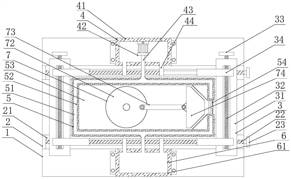
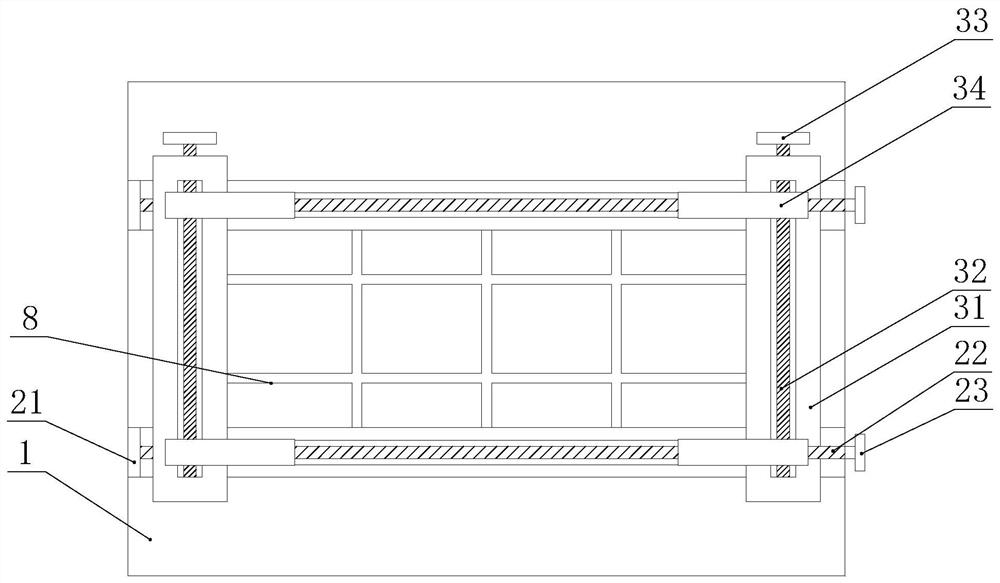
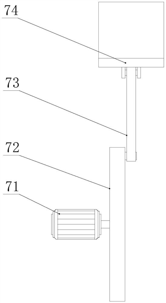
[0028] Example: such as Figure 1-6 As shown, a relay with a strong heat dissipation effect of the present invention includes a base 1, a limit mechanism 2 is provided on the top of the base 1, the position of both ends of the relay 5 is limited by the limit mechanism 2, and a clamping mechanism is provided on the top of the limit mechanism 2. Mechanism 3 clamps the other two ends of the relay 5 through the clamping mechanism 3, an oil cooling mechanism 4 is provided at one end of the base 1, through the oil cooling mechanism 4, cooling oil is provided for the internal oil storage chamber 52 of the relay 5, and the limit mechanism 2 is provided in the middle There is a relay 5, the end of the base 1 away from the oil cooling mechanism 4 is provided with a storage mechanism 6, which is convenient for storing heated cooling oil, and the inside of the relay 5 is equipped with an air cooling mechanism 7, which continuously extracts air into and out of the air, which is convenient f...


PUM


Abstract

The invention discloses a relay with a strong heat dissipation effect, and the relay comprises a base, a limiting mechanism is arranged at the top of the base, a clamping mechanism is arranged at the top of the limiting mechanism, an oil cooling mechanism is at one end of the base, a relay is arranged in the middle of the limiting mechanism, a storage mechanism is arranged at the end, away from the oil cooling mechanism, of the base, and an air cooling mechanism is arranged in the relay, a heat dissipation frame is disposed at the top of the base, the relay comprises an inner cavity, the air cooling mechanism comprises a motor, the motor is fixedly connected into the inner cavity, the output end of the motor is fixedly connected with a rotating disc, one end of the rotating disc is movably connected with a movable shaft through a center shaft, and the end, away from the rotating disc, of the movable shaft is movably connected with a movable block. The relay with a strong heat dissipation effect has the advantages that: a first handle of the limiting mechanism is rotated to drive a sliding block to move, so that a second sliding rail fixedly connected to the top of the sliding block moves to clamp the two ends of the relay, a second handle of the clamping mechanism is rotated to drive the clamping block to move to clamp the other two ends of the relay, and disassembly and assembly of the relay are facilitated.

Description

technical field [0001] The invention relates to a heat dissipation device, in particular to a relay with a strong heat dissipation effect, and belongs to the technical field of relay equipment. Background technique [0002] The relay is an electrical device, usually used in the control circuit of industrial equipment. It is a device that uses a small current to control the operation of a large current. It plays the role of automatic adjustment, safety protection, conversion circuit, etc. in the circuit. It is a kind of very important control element. [0003] However, the heat dissipation effect of existing relays is poor, and long-term use can easily lead to damage to the device, or even melting of parts and equipment, resulting in danger. The heat dissipation structure of the relay is generally air-cooled to dissipate heat. The installation structure of the relay is complicated, and it cannot be replaced and disassembled quickly, which is not conducive to the use of the d...

Claims


Application Information

Patent Timeline
IPC IPC(8): H01H45/02H01H45/12
CPCH01H45/12H01H45/02
Inventor 陈建飞
Owner 东海县通灵电器有限公司
Learn More