
Optical camera assembly welding equipment

A technology of camera assembly and welding equipment, applied in welding equipment, metal processing equipment, soldering iron, etc., can solve the problems of inability to adjust, slow welding efficiency, and high solder joints

Inactive Publication Date: 2021-04-23
南京航煜智能科技有限公司
View PDF11 Cites 0 Cited by
  • Summary
  • Abstract
  • Description
  • Claims
  • Application Information

AI Technical Summary

Problems solved by technology

In the current industry, the light board wire terminals inside the camera are usually soldered with manual soldering iron tips. Manual soldering is not only slow in welding efficiency, but also has high solder points that are easy to burn the light-emitting device; there are also mechanical welding equipment in the industry, but the welding angle is fixed. It cannot be adjusted, which makes the device have certain limitations

Method used


Image

  • Optical camera assembly welding equipment
  • Optical camera assembly welding equipment
  • Optical camera assembly welding equipment

Examples


Embodiment Construction

[0017] The following will clearly and completely describe the technical solutions in the embodiments of the present invention with reference to the accompanying drawings in the embodiments of the present invention. Obviously, the described embodiments are only some, not all, embodiments of the present invention. Based on the embodiments of the present invention, all other embodiments obtained by persons of ordinary skill in the art without making creative efforts belong to the protection scope of the present invention.

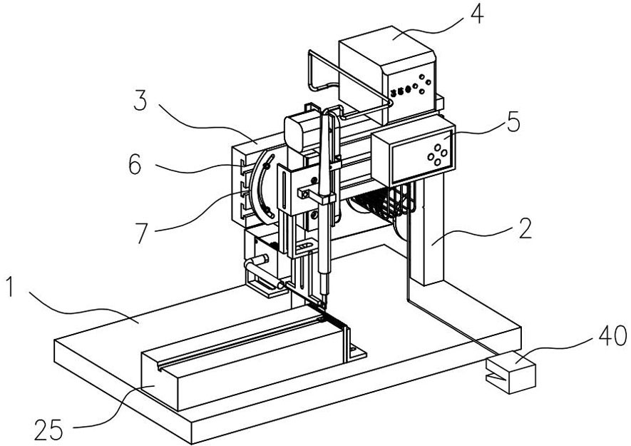
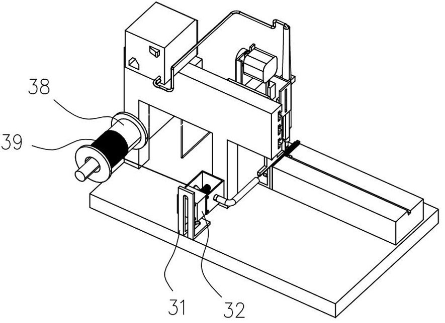
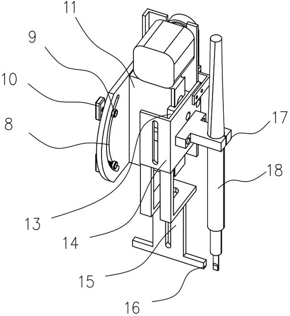
[0018] see Figure 1 to Figure 6 , the present invention provides a technical solution: an optical camera assembly welding equipment, including a base 1, the upper surface of the right side of the base 1 is vertically fixedly installed with a pillar 2; the upper end of the pillar 2 is fixedly installed with an adjustment plate 3; the adjustment plate 3 The upper end of the adjustment plate 3 is fixedly installed with a welding machine 4; the front side wall of...


PUM


Abstract

The invention relates to the related technical field of optical camera production and manufacturing, in particular to optical camera assembly welding equipment. A supporting column is vertically and fixedly installed on the upper surface of the right side of a base, an adjusting plate is fixedly mounted at the upper end of the supporting column, and a welding machine is fixedly mounted at the upper end of the adjusting plate; a control box is fixedly mounted on the front side wall of the right end of the adjusting plate, sliding grooves are uniformly formed in the front side wall of the adjusting plate at intervals, and a mounting plate is arranged on the front side wall of the adjusting plate; arc-shaped grooves are symmetrically formed in the front side wall of the mounting plate in a penetrating manner; a tensioning screw is mounted in each arc-shaped groove; a clamping block is connected and mounted on each tensioning screw, and the clamping blocks are clamped in the sliding grooves; and a sliding rail is vertically and fixedly mounted in the middle of the front side wall of the mounting plate, a vertical plate is vertically and fixedly mounted on the front side wall of the right end of the mounting plate, and a sliding block is clamped and mounted at the front end of the sliding rail. According to the optical camera assembly welding equipment, the welding efficiency is high, soldering tin butt joint is accurate, and the angle of a welding table can be adjusted.

Description

technical field [0001] The invention belongs to the technical field related to the production and manufacture of optical cameras, and in particular relates to welding equipment for optical camera components. Background technique [0002] The control board and wires inside the camera are welded together by heating and melting tin bars. In the past, when technology was not developed, welding was usually done manually. However, with the development of technology and the improvement of technical level, manual welding is gradually Replaced by mechanical soldering equipment, mechanical soldering equipment can perform automatic feeding and alignment welding, and the efficiency is not comparable to that of manual labor. In the current industry, the light board wire terminals inside the camera are usually soldered with manual soldering iron tips. Manual soldering is not only slow in welding efficiency, but also has high solder points that easily burn the light-emitting device; there ...

Claims


Application Information

Patent Timeline
IPC IPC(8): B23K3/02B23K3/08
CPCB23K3/02B23K3/08
Inventor 陈鹏赵亚南王成陈亚
Owner 南京航煜智能科技有限公司
Learn More