Fast forward device with hydraulic fertilizer pushing mechanism

A hydraulic and hydraulic valve technology, applied in the field of fast-forward devices, can solve problems such as affecting the effect of soil fertilization, large gaps in the fertilizer box, uneven soil fertilization, etc.

Pending Publication Date: 2021-04-23
HEILONGJIANG PROV AGRI MACHINERY ENG SCI INST
View PDF0 Cites 0 Cited by
  • Summary
  • Abstract
  • Description
  • Claims
  • Application Information

AI Technical Summary

Problems solved by technology

[0005] The invention solves the phenomenon that when the existing organic fertilizer applicator is loaded with organic fertilizer, there is a large gap before and after the fertilizer box, and the fertilizer pushing mechanism will appear uneven during fertilization due to the unevenness of the fertilizer in the fertilizer box. The phenomenon of accumulation of materials or little materials thrown leads to uneven fertilization of the whole land and affects the overall fertilization effect of the land. Aiming at the deficiencies of the prior art, the present invention discloses "a fast-forward device of a hydraulic fertilizer pushing mechanism"

Method used


Image

  • Fast forward device with hydraulic fertilizer pushing mechanism
  • Fast forward device with hydraulic fertilizer pushing mechanism
  • Fast forward device with hydraulic fertilizer pushing mechanism

Examples


specific Embodiment approach 1

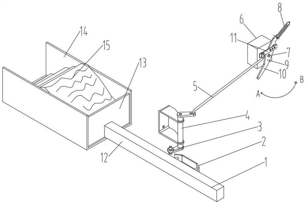
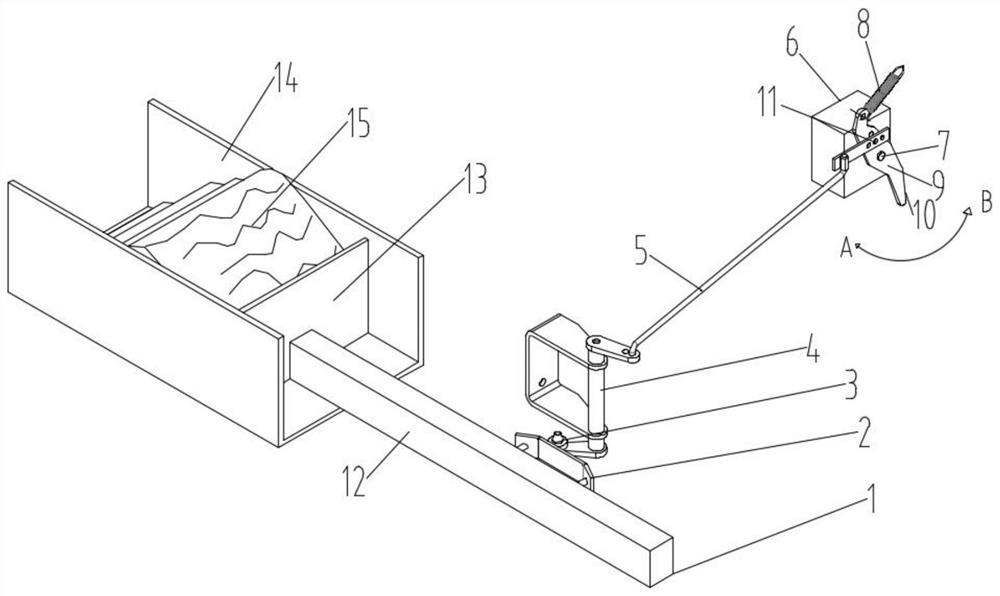
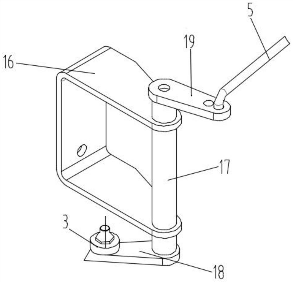
[0022] Specific implementation mode one: combine Figure 1-Figure 3 Describe this embodiment, a fast-forward device of a hydraulic fertilizer pushing mechanism in this embodiment, including a fertilizer pushing mechanism 1, a guide rail 2, a pulley 3, a guiding actuator 4, a pull rod 5, a hydraulic valve body 6, and a hydraulic valve rotor 7 And the executive rod 9, the guide rail 2 is fixedly installed on the fat pushing mechanism 1, the pulley 3 is rotatably installed on the guide actuator 4, the other end of the guide actuator 4 is equipped with a pull rod 5, and the other end of the pull rod 5 is fixedly connected with the actuator rod 9 , the hydraulic valve body 6 is equipped with a hydraulic valve rotating core 7, the executive rod 9 is fixedly installed on the hydraulic valve rotating core 7, the fertilizer pushing mechanism 1 is fixedly connected with the hydraulic mechanism, the hydraulic mechanism is an existing hydraulic push rod, and the hydraulic valve body 6. Co...

specific Embodiment approach 2

[0023] Specific implementation mode two: combination Figure 1-Figure 3 Describe this embodiment, a fast-forward device of a hydraulic fat pushing mechanism in this embodiment, one end of the actuator rod 9 is fixedly connected to a spring 8, the other end of the spring 8 is fixedly placed, and is fixedly installed at the end of the actuator rod 9 There is a spring 8, and the other end of the spring 8 is fixed. When the fertilizer pushing mechanism 1 continues to push forward to the middle part, there is no longer a large gap in the fertilizer box 14, the guide rail 2 and the pulley 3 are no longer in contact, and the spring 8 shrinks and pulls to execute Rod 9 restores the actuator rod 9 to its original position, and the actuator rod 9 drives the hydraulic valve core 7 to return to the original position. The hydraulic valve body 6 controls the hydraulic mechanism to restore the initial flow rate, so that the fertilizer pushing mechanism 1 advances at a constant speed according...

specific Embodiment approach 3

[0024] Specific implementation mode three: combination Figure 1-Figure 3 Describe this embodiment, a fast-forward device of a hydraulic fat pushing mechanism in this embodiment, the actuator rod 9 has a pointer 10, and the actuator rod 9 is processed with a pointer 10, and the hydraulic valve body can be understood according to the direction of the pointer 10. 6. Control the flow of the hydraulic mechanism. When the pointer 10 points to the A direction, the hydraulic mechanism drives the fat pushing mechanism 1 to advance at a constant speed. When the pointer 10 points to the B direction, the hydraulic valve body 6 controls the hydraulic mechanism to drive the fat pushing mechanism 1 to accelerate.


PUM


Abstract

The invention discloses a fast forward device with a hydraulic fertilizer pushing mechanism, and belongs to the field of agricultural machinery. The fast forward device solves the problem that when an organic fertilizer spreader loads organic fertilizer, large gaps appear in front of and behind a fertilizer box, and no material or fewer materials are spread during fertilization due to the large gaps. The fast forward device comprises a fertilizer pushing mechanism, a guide rail, a pulley, a guide executing mechanism, a pull rod, a hydraulic valve body, a hydraulic valve rotating core and an executing rod, the guide rail is fixedly mounted on the fertilizer pushing mechanism, the pulley is rotatably mounted on the guide executing mechanism, the pull rod is mounted at the other end of the guide executing mechanism, and the other end of the pull rod is fixedly connected with the executing rod; and the hydraulic valve rotating core is installed on the hydraulic valve body, and the executing rod is fixedly installed on the hydraulic valve rotating core. By means of the fast forward device, a fast forward mechanism for adjusting the hydraulic valve body is arranged, the pushing speed of the fertilizer pushing mechanism can be effectively controlled, the phenomenon that no material is scattered in the fertilization process is avoided, and the land fertilization effect is improved.

Description

technical field [0001] The invention relates to a fast-forward device of a hydraulic fertilizer pushing mechanism, which belongs to the field of agricultural machinery. Background technique [0002] Fertilization refers to the agricultural technical measures of applying fertilizers to the soil or spraying them on plants to provide the nutrients needed by plants and maintain and improve soil fertility. The main purpose of fertilization is to increase crop yield, improve crop quality, fertilize soil and improve economic benefits. Therefore, rational and scientific fertilization is one of the main means to ensure food security and maintain sustainable agricultural development. The main basis for fertilization is soil fertility level, crop type, target yield, climate environment and fertilizer characteristics, so as to select the appropriate fertilizer, estimate the amount of fertilizer required, and determine the time and mode of fertilization. According to different fertiliza...

Claims


Application Information

Patent Timeline
IPC IPC(8): A01C15/12
CPCA01C15/124
Inventor 吴昊钱晓辉陈伟旭许骁博李博金鹍鹏陈爱慧郭英洲徐冬张海滨王涛盛力伟田健
Owner HEILONGJIANG PROV AGRI MACHINERY ENG SCI INST
Why Eureka
Try Eureka