Pneumatic flange butterfly valve

A pneumatic flange butterfly and flange technology, applied in the direction of valve lift, valve details, valve devices, etc., can solve the problems that the valve plate 3 cannot rotate, cannot be used, and the connecting mechanism is rusted and damaged.

Pending Publication Date: 2021-04-20
无锡鑫明自控阀业有限公司
View PDF1 Cites 1 Cited by
  • Summary
  • Abstract
  • Description
  • Claims
  • Application Information

AI Technical Summary

Problems solved by technology

[0005] But above-mentioned technical scheme still has many shortcomings when practical application;
[0006] 1. Since the reference document uses the pneumatic flange butterfly valve, the gas flow counter 12 and the gas storage tank 14 are used to precisely control the flow, thereby increasing the accuracy of the rotation angle of the valve plate 3. Since the general valves are used in water Therefore, when the pneumatic flange butterfly valve is used for a long time, the gas flow counter 12 will be flooded, which will be damaged and cannot be used;
[0007] 2. Since the comparison document is connected to the valve plate 3 through the pneumatic motor 7, when the pneumatic motor 7 is started, it will drive the valve plate 3 to rotate. Since the valve plate 3 is used to discharge and retain water, water will erode the valve during use. The plate 3 and the connecting mechanism will cause rust and damage to the connecting mechanism, etc., and eventually the valve plate 3 will not be able to rotate.

Method used


Image

  • Pneumatic flange butterfly valve
  • Pneumatic flange butterfly valve
  • Pneumatic flange butterfly valve

Examples


Embodiment Construction

[0027]Next, the technical solutions in the embodiments of the present invention will be apparent from the embodiment of the present invention, and it is clearly described, and it is understood that the described embodiments are merely embodiments of the present invention, not all of the embodiments. Based on the embodiments of the present invention, there are all other embodiments obtained without making creative labor without making creative labor premises.

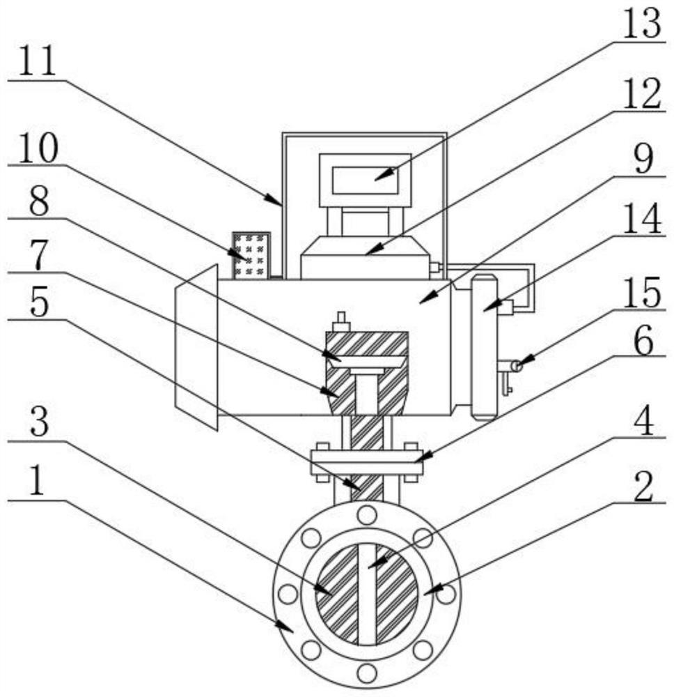
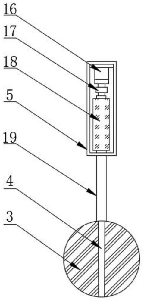
[0028]AppendFigure 1-6A pneumatic flange butterfly valve, including flange 1, seal ring 2, valve plate 3, valve groove 4 and inner rod 5, the top fixed set of inner rod 5 has Zhongmai 6, Zhongmado 6 The top is fixedly mounted with a pneumatic 7, and the internal activity of the pneumotor 7 is attached to the piston 8, and the top of the middle mailing 6 is fixedly mounted with a pneumatic device protective case 9. On one side of the pneumatic device protective case 9 fixedly mounted with a dry box 10. The top portion of the pneum...


PUM


Abstract

The invention discloses a pneumatic flange butterfly valve, and particularly relates to the field of butterfly valves. The pneumatic flange butterfly valve comprises a flange port, a sealing ring, a valve plate, a valve groove and an inner rod, wherein the top of the inner rod is fixedly sleeved with a middle flange; the top of the middle flange is fixedly provided with a pneumatic machine; a piston is movably installed in the pneumatic machine; a pneumatic device protection shell is fixedly installed at the top of the middle flange; and a drying box is fixedly installed on one side of the top of the pneumatic device protection shell. According to the pneumatic flange butterfly valve provided by the invention, by arranging a waterproof device, when the pneumatic flange butterfly valve is used, a gas flow counter and a gas storage tank are used for accurately controlling the flow, so that the accuracy of the rotating angle of the valve plate is improved; and due to the fact that a common valve is used underwater, the waterproof device is used for drying water in the counter and the periphery of the counter, so that the counter is prevented from being damaged, the problem that the accuracy of the valve plate is inaccurate is solved, the completeness of the counter is ensured, and meanwhile, the accuracy of the valve plate is also ensured.

Description

Technical field[0001]The present invention relates to the field of butterfly valve, and more particularly, the present invention specifically a pneumatic flange butterfly valve.Background technique[0002]Pneumatic flange butterfly valve, butterfly valve with a pneumatic actuator, the actuator is relatively fast, and does not require workers to affiliate, to a large extent, the human resources and time, simple structure, small weight, low cost, low cost This feature is particularly remarkable, and the installation of the two-five-way solenoid valve control is convenient, and the flow medium, the fluid resistance is smaller, and the incentive disc valve is more effective. Large, fast and powerful, the disc is rotated 90 angle to complete the opening and closing, due to the opposite direction of the disc two-sided disc handle die, the resulting torque direction, thus the opening and closing moment is small, the low pressure can be realized under low pressure Good seal, disc valve sealin...

Claims


Application Information

Patent Timeline
Patent Type & Authority Applications(China)
IPC IPC(8): F16K1/22F16K31/12F16K37/00
Inventor 朱振华
Owner 无锡鑫明自控阀业有限公司
Why Eureka
Try Eureka