Special sealing dismounting tool for equipment machinery
A technology for disassembling tools and machinery, which is applied in the direction of manufacturing tools and hand-held tools, etc. It can solve the problems of inability to disassemble and replace parts of the head, single use structure, and low use strength, so as to achieve diversified structures, high use strength, non-wear effect
- Summary
- Abstract
- Description
- Claims
- Application Information
AI Technical Summary
Problems solved by technology
Method used
Image
Examples
Embodiment 1
[0026] Embodiment 1, the slide rail 407 is located on the outer wall of the positioning rod 401, the slider 402 is located on the outside of the slide rail 407, the dismounting rod 405 is located at one end of the positioning rod 401, the thread 406 is located on the outer wall of the dismounting rod 405, and the snap frame 403 is located around the slider 402, the buckle 404 is located on one side of the engaging frame 403, the outer wall of the positioning pole 401 is movably connected with the inner wall of the sliding block 402 through the slide rail 407, and the sliding block 402 and the engaging frame 403 are arranged There is a fixed block, the slider 402 is fixedly connected to one side of the engaging frame 403 through the fixed block, a welding block is arranged between the positioning pole 401 and the dismounting rod 405, and one end of the positioning pole 401 is connected to the dismounting pole by the welding block. One end of the loading rod 405 is fixedly connec...
Embodiment 2
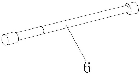
[0027] Embodiment 2, the rotating pin 601 is located at one end of the No. 1 handle 603, the rotating column 602 is located at one end of the No. 2 handle 605, the first detachable block 604 is located at the other end of the No. 1 handle 603, and the No. 2 detachable The stopper 606 is located at the other end of the No. 2 grip bar 605, and one end of the No. 1 grip bar 603 is flexibly connected with one end of the No. 2 grip bar 605 through a rotating pin 601 and a rotating column 602. The No. 1 grip bar 603 is connected to the first detachable There is a No. 1 block between the stoppers 604, and one end of the No. 1 handle 603 is detachably connected to one end of the first detachable block 604 through the No. 1 block. The No. 2 handle 605 and the No. 2 detachable There is a No. 2 block between the stoppers 606, and one end of the No. 2 handle bar 605 is detachably connected to one end of the No. 2 detachable block 606 through the No. 2 block, which can facilitate the foldin...
Embodiment 3
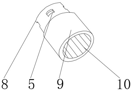
[0028]Embodiment 3, the rust removal layer 902 is located on the inner wall of the self-cleaning layer 901, the reinforcement layer 903 is located on the inner wall of the rust removal layer 902, the wear-resistant layer 904 is located on the inner wall of the reinforcement layer 903, and the sealing layer 905 is located on the inner wall of the wear-resistant layer 904. There is a No. 1 pouring block between the cleaning layer 901 and the derusting layer 902. The inner wall of the self-cleaning layer 901 is fixedly connected with the outer wall of the derusting layer 902 through the No. 1 pouring block. No. 1 pouring block, the inner wall of the wear-resistant layer 904 is fixedly connected with the inner surface of the sealing layer 905 through the No. 2 pouring block, which can increase the stability of head positioning, has higher service strength, is not easy to wear, and is simple and practical.
PUM
 Abstract
Description
Claims
Application Information
 - Generate Ideas
- Intellectual Property
- Life Sciences
- Materials
- Tech Scout
- Unparalleled Data Quality
- Higher Quality Content
- 60% Fewer Hallucinations
Browse by: Latest US Patents, China's latest patents, Technical Efficacy Thesaurus, Application Domain, Technology Topic, Popular Technical Reports.
© 2025 PatSnap. All rights reserved.Legal|Privacy policy|Modern Slavery Act Transparency Statement|Sitemap|About US| Contact US: help@patsnap.com


