Supercharge Your Innovation With Domain-Expert AI Agents!

Double-waveband double-chirp microwave signal generating and transmitting device and method

A technology of microwave signal and chirp signal, which is applied in the field of microwave photonics, can solve the problems of signal power fading and difficulty in satisfying the practical application of microwave band signals at the same time, and achieve the effect of overcoming power fading

Active Publication Date: 2021-04-09
INST OF SEMICONDUCTORS - CHINESE ACAD OF SCI
View PDF4 Cites 2 Cited by
  • Summary
  • Abstract
  • Description
  • Claims
  • Application Information

AI Technical Summary

Problems solved by technology

[0004] The above schemes are limited by the multiplier frequency, and can only generate double-chirp signals with a fixed center frequency relationship (only double-frequency, double-frequency, etc.), which is difficult to meet the practical application of signals in various microwave bands at the same time.
In addition, the generation of microwave photonics signals usually requires long-distance optical fiber transmission, and ordinary single-mode optical fibers have dispersion effects, which will cause power attenuation due to dispersion effects during signal transmission.

Method used


Image

  • Double-waveband double-chirp microwave signal generating and transmitting device and method
  • Double-waveband double-chirp microwave signal generating and transmitting device and method
  • Double-waveband double-chirp microwave signal generating and transmitting device and method

Examples


Embodiment Construction

[0020] Hereinafter, embodiments of the present disclosure will be described with reference to the drawings. It should be understood, however, that these descriptions are exemplary only, and are not intended to limit the scope of the present disclosure. In the following detailed description, for purposes of explanation, numerous specific details are set forth in order to provide a thorough understanding of the embodiments of the present disclosure. It may be evident, however, that one or more embodiments may be practiced without these specific details. Also, in the following description, descriptions of well-known structures and techniques are omitted to avoid unnecessarily obscuring the concept of the present disclosure.

[0021] The terminology used herein is for the purpose of describing particular embodiments only, and is not intended to be limiting of the present disclosure. The terms "comprising", "comprising", etc. used herein indicate the presence of stated features, ...


PUM


Abstract

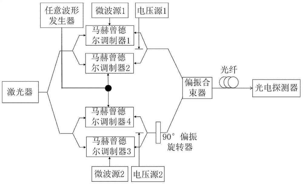
A double-waveband double-chirp microwave signal generation and transmission device comprises a laser used for generating an optical signal; a first modulation module which is used for modulating a microwave signal emitted by the first microwave source and a signal emitted by the arbitrary waveform generator onto an optical signal to generate a first modulated optical signal; a second modulation module which is used for modulating the microwave signal emitted by the second microwave source and the signal emitted by the arbitrary waveform generator to an optical signal to generate a second modulated optical signal, wherein the frequencies of the microwave signals generated by the first microwave source and the second microwave source are different; a 90-degree polarization rotator, which is used for enabling the first modulation optical signal and the second modulation optical signal to be in an orthogonal polarization state; and a photoelectric detector, which is used for carrying out photoelectric conversion on the first modulation optical signal and the second modulation optical signal and then superposing to obtain a dual-band dual-chirp signal. The device provided by the invention is simple in structure, and can overcome a power fading phenomenon caused by optical fiber dispersion in a long-distance optical fiber transmission process.

Description

technical field [0001] The present disclosure relates to the technical field of microwave photonics, in particular to a dual-band dual-chirped microwave signal generation and transmission device and method. Background technique [0002] With the continuous development of modern radar technology, the radar system has evolved from a single frequency band to a multi-band and multi-functional direction. Compared with the single-chirp signal, the double-chirp signal can overcome the Doppler-range coupling effect and can be applied to radar ranging and velocity measurement. The double-chirp signal also has good pulse compression characteristics, and can be widely used in the signal source of long-range early warning radar and high-resolution radar system. [0003] Usually the double-chirp signal can be realized by traditional electronic methods and photonics microwave signal generation technology. However, due to the limitation of the bottleneck of electronic devices, the bandwi...

Claims


Application Information

Patent Timeline
Patent Type & Authority Applications(China)
IPC IPC(8): H04B10/2513H04B10/50H04B10/516
CPCH04B10/25137H04B10/503H04B10/516
Inventor 王璐李伟孙文惠李光毅李明祝宁华
Owner INST OF SEMICONDUCTORS - CHINESE ACAD OF SCI
Features
  • R&D
  • Intellectual Property
  • Life Sciences
  • Materials
  • Tech Scout
  • Unparalleled Data Quality
  • Higher Quality Content
  • 60% Fewer Hallucinations
Learn More