Wind power generation device

A wind power generation device, a technology in the middle position, which is applied in the directions of wind power generation, wind turbines, wind turbine combinations, etc., can solve the problems of inability to prevent wind and sand, affect the installation effect, and have incomplete functions, so as to facilitate stable installation, It is beneficial to shake off and increase the effect of shaking amplitude

Inactive Publication Date: 2021-04-09
苏州波粒新能源科技有限公司
View PDF0 Cites 0 Cited by
  • Summary
  • Abstract
  • Description
  • Claims
  • Application Information

AI Technical Summary

Problems solved by technology

[0002] Wind generators are widely promoted and used. With the help of wind force, the blades are rotated, which drives the inner rotor to rotate, thereby cutting the magnetic induction line to achieve the effect of magnetically generating electricity, thereby generating electricity. It is often installed in areas with high air velocity, but existing The wind power generation device in the technology cannot play the function of preventing wind and sand when it is used in the wind and sand area. Specifically, it cannot block the sand, weaken the wind force, and has incomplete functions. Moreover, the wind and sand area is often sandy soil, and it is easy to occur after a long time after installation. Unstable phenomenon, affecting the installation effect

Method used


Image

  • Wind power generation device
  • Wind power generation device
  • Wind power generation device

Examples


Embodiment Construction

[0025] The following description serves to disclose the present invention to enable those skilled in the art to carry out the present invention. The preferred embodiments described below are only examples, and those skilled in the art can devise other obvious variations.

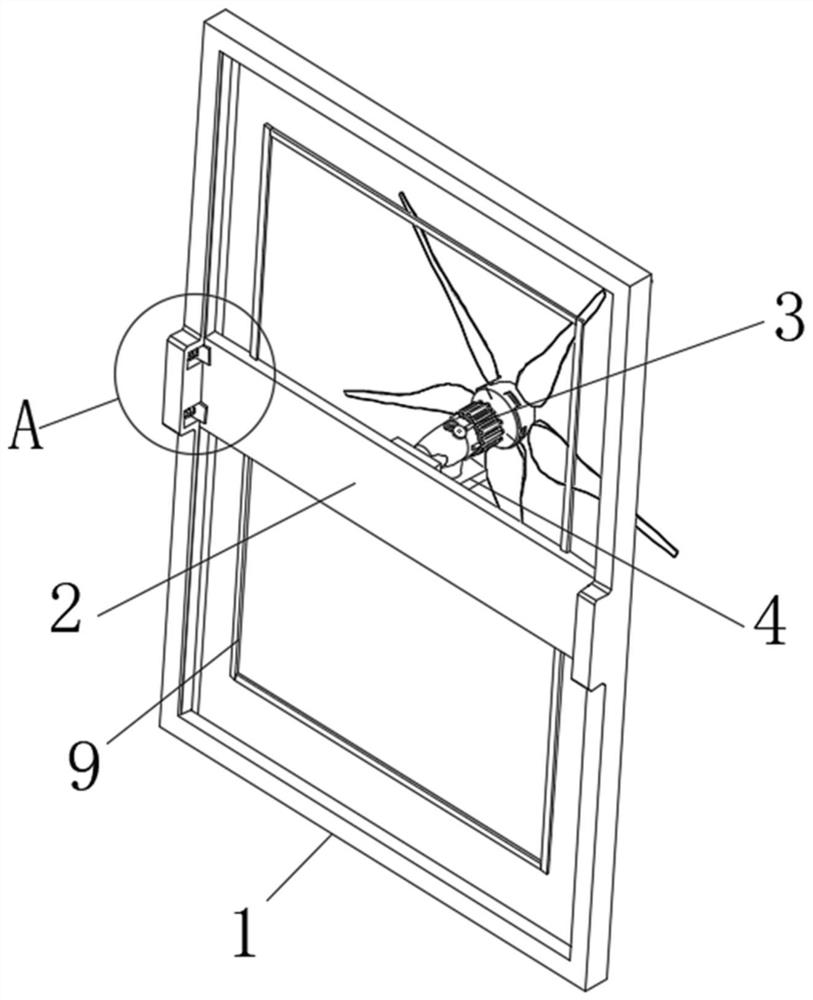
[0026] Such as Figure 1-Figure 7 The shown wind power generation device includes a supporting frame 1, a connecting plate 2 is movably installed in the middle position inside the supporting frame 1, the outer surfaces on both sides of the connecting plate 2 extend out from the snap-in blocks 8, and the inner walls on both sides of the supporting frame 1 There is a movable groove 6 for snap-in block 8 to be snapped in on the top, and a vibrating spring 7 is arranged on the inner side of the movable groove 6. Connection, the front end surface of the connection plate 2 is fixedly installed with the wind power generator 3 through the mounting seat 4, and the sand prevention net 10 is arranged between the upper...


PUM


Abstract

The invention relates to the field of wind power generation devices, in particular to a wind power generation device which comprises a supporting frame. A connecting plate is movably installed in the middle of the inner side of the supporting frame, clamping blocks extend out of the outer surfaces of the two sides of the connecting plate, and movable grooves allowing the clamping blocks to be movably clamped therein are formed in the inner walls of the two sides of the supporting frame. Shaking springs are arranged on the inner sides of the movable grooves, the two ends of the shaking springs are fixedly connected with the rear end faces of the clamping blocks and the inner walls of the movable grooves correspondingly, a wind driven generator is fixedly mounted on the front end face of the connecting plate through a mounting base, sand prevention nets are arranged between the upper end face and the lower end face of the connecting plate and the inner side of the supporting frame, and the sand prevention nets are fixedly connected with the top face of the inner side of the supporting frame and the outer surface of the connecting plate. The wind power generation device can be used in a sandy area, the effects of blocking sand and weakening wind are achieved while power generation is conducted, sand and wind can be collected, and stable installation at sandy soil is facilitated.

Description

technical field [0001] The invention relates to the field of wind power generation devices, in particular to a wind power generation device. Background technique [0002] Wind generators are widely promoted and used. With the help of wind force, the blades are rotated, which drives the inner rotor to rotate, thereby cutting the magnetic induction line to achieve the effect of magnetically generating electricity, thereby generating electricity. It is often installed in areas with high air velocity, but existing The wind power generation device in the technology cannot play the function of preventing wind and sand when it is used in the wind and sand area. Specifically, it cannot block the sand, weaken the wind force, and has incomplete functions. Moreover, the wind and sand area is often sandy soil, and it is easy to occur after a long time after installation. Unstable phenomena affect the installation effect. Contents of the invention [0003] The object of the present in...

Claims


Application Information

Patent Timeline
Patent Type & Authority Applications(China)
IPC IPC(8): F03D9/25F03D80/00B01D46/48B01D46/10B01D46/00
CPCF03D9/25F03D80/00B01D46/48B01D46/10B01D46/76Y02E10/72
Inventor 刘涛
Owner 苏州波粒新能源科技有限公司
Why Eureka
Try Eureka