
Building construction material mixing device

A material mixing and building construction technology, which is applied in the direction of mixers, mixers with rotating stirring devices, transportation and packaging, etc., can solve the problems affecting the mixing efficiency of materials, and achieve the goal of improving mixing efficiency, preventing fluidity and avoiding clogging Effect

Pending Publication Date: 2021-04-09
孙冬叶
View PDF4 Cites 2 Cited by
  • Summary
  • Abstract
  • Description
  • Claims
  • Application Information

AI Technical Summary

Problems solved by technology

[0002] Mixing equipment is a commonly used equipment in the construction process. It is mainly used to mix some raw materials. When the existing material mixing device is mixing materials, a large amount of materials are accumulated in the mixing chamber, which seriously affects the mixing efficiency of materials.

Method used


Image

  • Building construction material mixing device
  • Building construction material mixing device
  • Building construction material mixing device

Examples


Embodiment 1

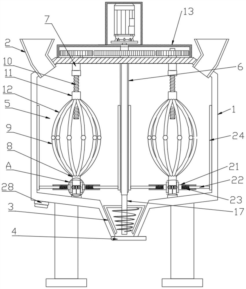
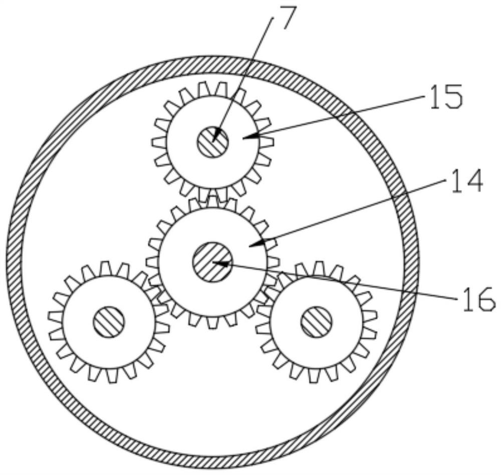
[0023] see Figure 1-4 , a material mixing device for building construction, comprising a housing 1, the top surface of the housing 1 is symmetrically provided with a feed channel 2, and the bottom of the housing 1 is provided with a discharge channel 3, and the discharge channel 3 It is in the shape of a cone, and the bottom of the discharge channel 3 is hinged with an on-off valve 4. The inside of the housing 1 is divided into a plurality of stirring chambers 5 through a partition 6. The stirring chamber 5 is provided with a stirring mechanism. The top of the body 1 is provided with a driving mechanism that drives multiple stirring mechanisms to operate simultaneously. The stirring mechanism includes a first rotating shaft 7, a second rotating shaft 8, a stirring paddle 9, a threaded rod 10 and a threaded sleeve 11. The first rotating shaft 7 Rotately connected with the top surface of the housing 1, the threaded rod 10 is fixed on the bottom of the first rotating shaft 7, an...

Embodiment 2

[0028] This embodiment describes the scraping mechanism in detail on the basis of Embodiment 1, specifically:

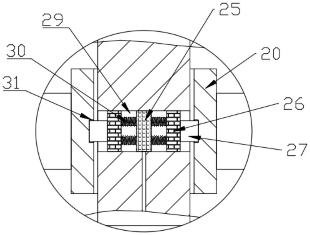
[0029]The scraping mechanism includes a sleeve block 20, a telescopic sleeve 21 and a telescopic rod 22, the sleeve block 20 is installed on the second rotating shaft 8 through a connecting assembly, and the outer surface of the sleeve block 20 is fixed with a telescopic sleeve 21 One end of the telescopic rod 22 is slidably connected in the telescopic sleeve 21, and the telescopic rod 22 is provided with a first spring 23 between the telescopic sleeves 21, and the other end of the telescopic rod 22 is fixedly provided with a scraper 24. The scraper 24 is rotatably connected with the inner wall of the housing 1 and the partition plate 6; the connecting assembly includes an electromagnet 25, a permanent magnet 26, a limit block 27 and a switch button 28, and the switch button 28 is arranged on the bottom surface of the stirring tank. The second rotating shaft 8 is loc...


PUM


Abstract

The invention relates to the field of building construction equipment, in particular to a building construction material mixing device which comprises a shell, feeding channels are symmetrically formed in the top surface of the shell, a discharging channel is formed in the bottom of the shell, the discharging channel is conical, and a switch valve is hinged to the bottom of the discharging channel; the interior of the shell is divided into a plurality of stirring bins through partition plates, a stirring mechanism is arranged in each stirring bin, a driving mechanism for driving the multiple stirring mechanisms to operate at the same time is arranged at the top of the shell, and by arranging the multiple stirring bins and the multiple stirring mechanisms, the driving mechanism can drive the multiple stirring mechanisms to operate at the same time. In cooperation with the separation effect of the multiple stirring bins, materials in the shell are separated and stirred, and the phenomenon that the materials cannot be uniformly mixed due to accumulation of a large number of materials is avoided.

Description

technical field [0001] The invention relates to the field of building construction equipment, in particular to a material mixing device for building construction. Background technique [0002] Mixing equipment is a commonly used equipment in the construction process. It is mainly used to mix some raw materials. When the existing material mixing device is mixing materials, a large amount of materials are accumulated in the mixing chamber, which seriously affects the mixing efficiency of materials. Contents of the invention [0003] The object of the present invention is to provide a material mixing device for building construction to solve the problems raised in the above-mentioned background technology. [0004] To achieve the above object, the present invention provides the following technical solutions: [0005] A material mixing device for building construction, comprising a shell, the top surface of the shell is symmetrically provided with a feed channel, and the bott...

Claims


Application Information

Patent Timeline
Patent Type & Authority Applications(China)
IPC IPC(8): B01F13/10B01F15/00B01F7/18
CPCB01F33/81B01F35/123B01F27/90
Inventor 孙冬叶
Owner 孙冬叶
Learn More