
Automatic feeding and discharging punching die for automobile parts

A technology for auto parts, feeding and discharging materials, applied in the direction of piercing tools, feeding devices, manufacturing tools, etc., can solve the problems of high energy consumption, high cost of transportation equipment, low efficiency of successive punching of fixed molds, etc., and increase production efficiency , Increase reliability, accurate and timely automatic feeding effect

Inactive Publication Date: 2021-04-06
YUHUAN QIYUAN TECH CO LTD
View PDF0 Cites 1 Cited by
  • Summary
  • Abstract
  • Description
  • Claims
  • Application Information

AI Technical Summary

Problems solved by technology

[0004] The purpose of the present invention is to solve the shortcomings of the prior art, such as the low efficiency of successive punching of fixed dies, the need to increase the cost of transportation equipment and high energy consumption for continuous punching, and propose a punching die for automatic feeding and discharging of auto parts

Method used


Image

  • Automatic feeding and discharging punching die for automobile parts
  • Automatic feeding and discharging punching die for automobile parts
  • Automatic feeding and discharging punching die for automobile parts

Examples


Embodiment Construction

[0025] The following will clearly and completely describe the technical solutions in the embodiments of the present invention with reference to the accompanying drawings in the embodiments of the present invention. Obviously, the described embodiments are only some, not all, embodiments of the present invention.

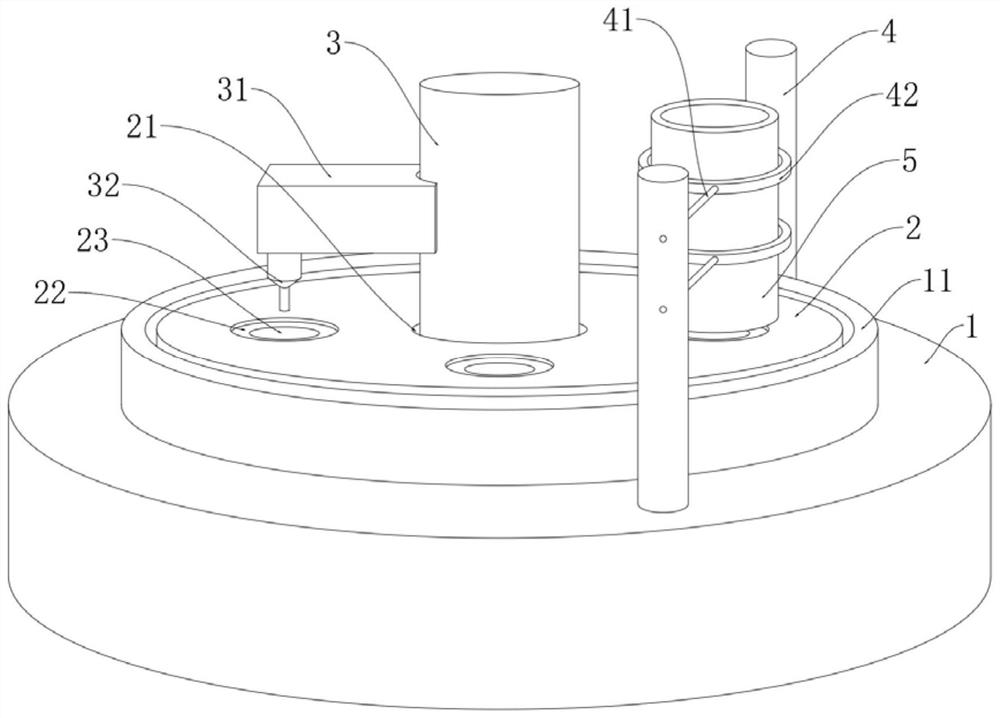
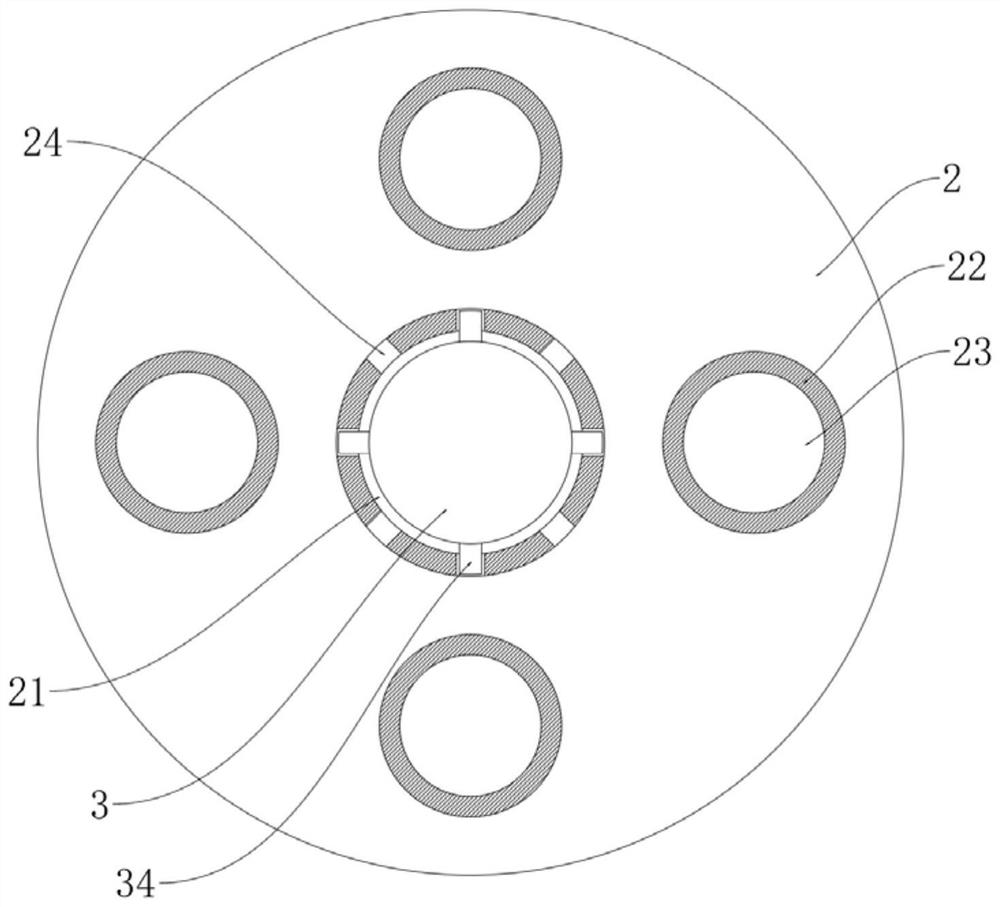
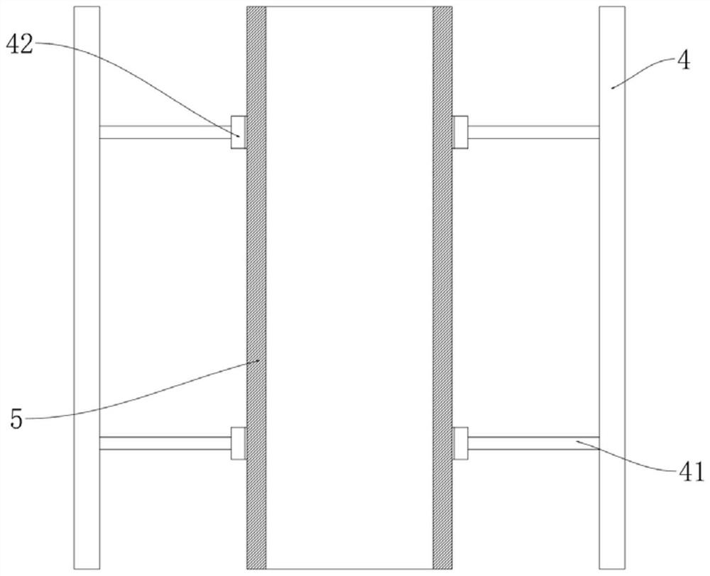
[0026] refer to Figure 1-6 , a kind of punching die for automatic feeding and discharging of auto parts, including a base 1, a support ring 11 is installed on the upper surface of the base 1, a die disc 2 is mounted on the support ring 11, and a plurality of die discs are symmetrically arranged on the upper surface of the die disc 2. The trough 22, the bottom of each trough 22 is provided with a punching hole 23, the center of the die plate 2 is provided with a control hole 21, the center of the base 1 is provided with a control hydraulic chamber 12, and the control hydraulic chamber 12 is slidingly inserted into the hydraulic pressure chamber. Rod 3, the upper end ...


PUM


Abstract

The invention discloses an automatic feeding and discharging punching die for automobile parts. The automatic feeding and discharging punching die comprises a base, wherein a backing ring is mounted on the upper surface of the base, a punching die disc is rotatably mounted on the backing ring, a plurality of material grooves are symmetrically formed in the upper surface of the punching die disc, and a punching hole channel is formed in the groove bottom of each material groove; and a control hole is formed in the center of the punching die disc, a control hydraulic cavity is formed in the center of the base, a hydraulic rod is inserted into the control hydraulic cavity in a sliding mode, the upper end of the hydraulic rod does not penetrate through the control hole in a contact mode, extends to the position above the punching die disc and is provided with a cross arm, and a punching drill is mounted on the lower surface of the cross arm. The punching die disc intermittently rotates and a discharging rod vertically moves through vertical movement of the hydraulic rod, so that the material grooves can cooperate with material barrels to achieve automatic feeding, a discharging rod can cooperate with the punching hole channel and the material grooves to achieve automatic discharging, extra equipment does not need to be added, the production efficiency is improved, more energy is saved, and the cost is lower.

Description

technical field [0001] The invention relates to the field of molds for auto parts, in particular to a punching die for automatic feeding and discharging of auto parts. Background technique [0002] Auto parts include many connectors, and the connections between the connectors are usually locked by screws or bolts. Therefore, it is necessary to punch holes on the connectors to facilitate the installation of screws and bolts. [0003] Existing punching dies are usually fixed dies that are punched successively by a hydraulic punching machine, and the punching speed is low, while continuous punching with chain belt conveyance requires additional transportation equipment, which increases both cost and energy consumption. Contents of the invention [0004] The purpose of the present invention is to solve the shortcomings of the prior art, such as the low efficiency of successive punching of fixed dies, the need to increase the cost of transportation equipment and high energy con...

Claims


Application Information

Patent Timeline
Patent Type & Authority Applications(China)
IPC IPC(8): B21D28/34B21D43/14B21D45/00
CPCB21D28/34B21D43/14B21D45/006
Inventor 何婷
Owner YUHUAN QIYUAN TECH CO LTD
Learn More