Accurate alignment and segmented lowering device for large-diameter super-long reinforcement cage and using method

An ultra-long steel cage and large-diameter technology is applied in construction, sheet pile walls, and foundation structure engineering. It can solve problems such as the difficulty in meeting the requirements for the length of the crane arm and the difficulty in hoisting and lowering the ultra-long steel cage, so as to achieve easy transportation and portability. Easy and quick installation

Pending Publication Date: 2021-04-02
ANHUI SHUIAN CONSTR GRP CO LTD +1
View PDF0 Cites 2 Cited by
  • Summary
  • Abstract
  • Description
  • Claims
  • Application Information

AI Technical Summary

Problems solved by technology

[0003] When carrying out pile foundation construction, due to the deep hole pile depth, it is difficult to hoist and lower the super-long steel cage with the existing technology, and the length of the crane arm is difficult to meet the requirements. The assembly of subsections needs to solve the problem of precise alignment between each section. The current technology mainly relies on manual observation and alignment. It is difficult to perform alignment in a small space such as a pile hole. For this reason, a large-diameter and super-long steel cage is required. Alignment and Segmented Lowering

Method used


Image

  • Accurate alignment and segmented lowering device for large-diameter super-long reinforcement cage and using method
  • Accurate alignment and segmented lowering device for large-diameter super-long reinforcement cage and using method
  • Accurate alignment and segmented lowering device for large-diameter super-long reinforcement cage and using method

Examples


Embodiment Construction

[0040] The following will clearly and completely describe the technical solutions in the embodiments of the present invention with reference to the accompanying drawings in the embodiments of the present invention. Obviously, the described embodiments are only some, not all, embodiments of the present invention.

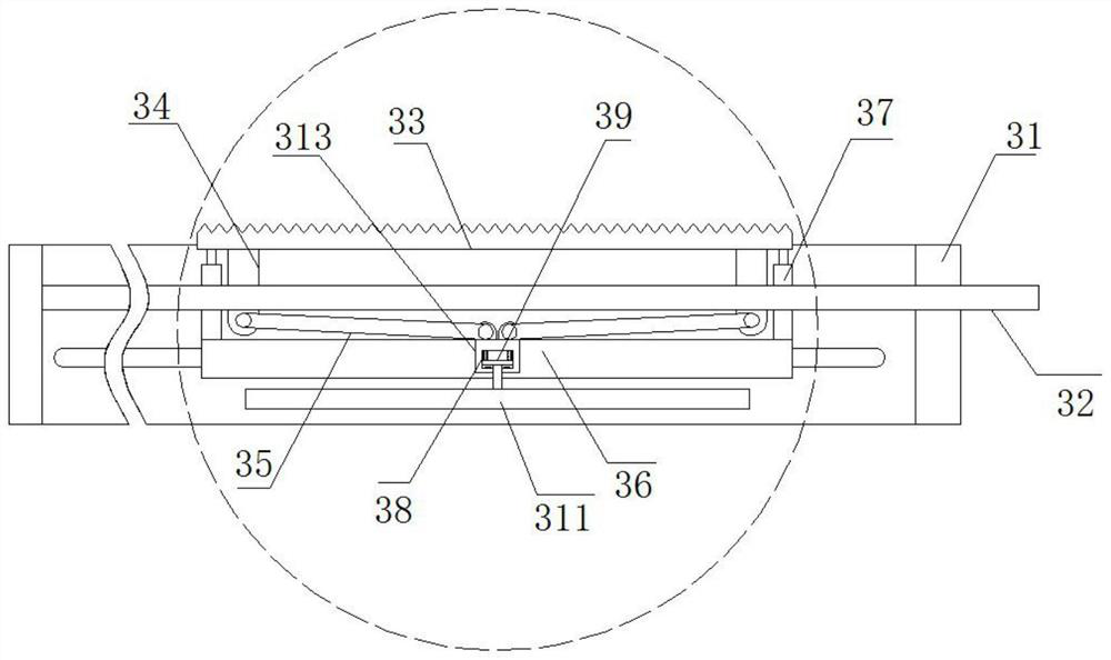
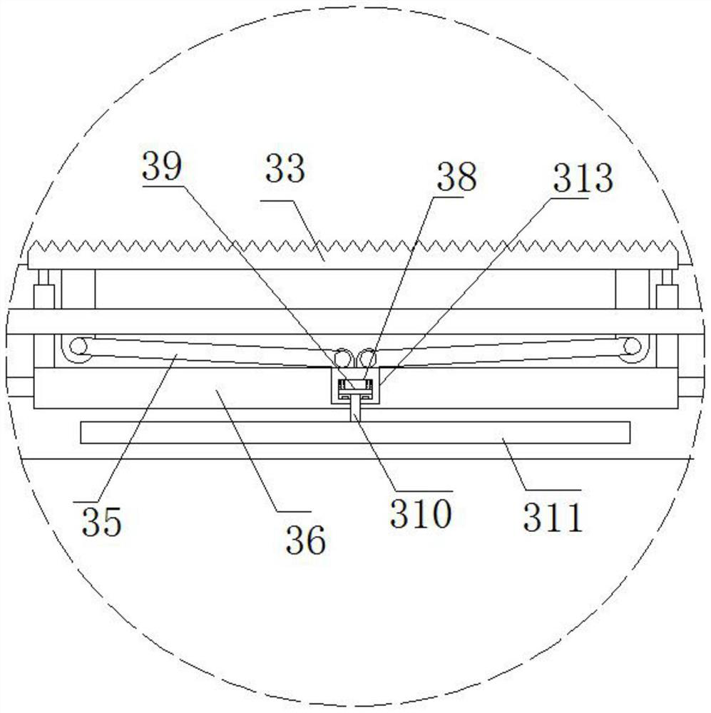
[0041] refer to Figure 1-7 , the device for precise alignment and segmental lowering of large-diameter and super-long steel cages, including a bottom support mechanism 1 arranged in a square shape, characterized in that the top of the bottom support mechanism 1 is slidably connected to a square-shaped moving mechanism 2, and the moving mechanism 2 The alignment mechanism 3 is slidingly socketed on the four sides, and the alignment mechanism 3 extends into the position of the inner ring of the moving mechanism 2 and is detachably connected with a docking mechanism 4;

[0042] The alignment mechanism 3 includes a frame 31 of a rectangular structure that is slidingly s...


PUM


Abstract

The invention belongs to the technical field of building construction, and particularly relates to an accurate alignment and subsection lowering device for a large-diameter super-long reinforcement cage and a using method. The following scheme is provided that the device comprises a bottom supporting mechanism arranged in a square shape; a moving mechanism of a square structure is slidably connected with the top of the bottom supporting mechanism; the four sides of the moving mechanism are sleeved with aligning mechanisms in a sliding mode; each aligning mechanism comprises a rectangular frameslidably connected with the moving mechanism in a sleeving mode; the frames are movably connected with rotating rods arranged in the length direction of the frames in a sleeving mode; and the tops, stretching into the inner rings of the frames, of the rotating rods are provided with a long-strip-shaped clamping plate arranged in the length direction of the frames. By means of the combined designof the accurate alignment and subsection lowering device for the large-diameter super-long reinforcement cage, installation is convenient and fast, transportation and carrying are convenient, meanwhile, and the device can be suitable for alignment and butt joint operation of the lower portions of the reinforcement cages in hole pile holes with different diameters; and the reinforcement cages and the hole pile holes are coaxial, so that the situation that the reinforcement cages are kept in a vertical state when located below is guaranteed, the operation is convenient, and the labor intensity of operators is reduced.

Description

technical field [0001] The invention relates to the technical field of building construction, in particular to a device for precise alignment and segmental lowering of a large-diameter and super-long reinforcement cage and a method for using it. Background technique [0002] Cast-in-place pile is a kind of pile made by forming holes in place and pouring concrete or reinforced concrete. Commonly used ones are: (1) Bored cast-in-place piles: Use auger drilling rigs, submersible drilling rigs, etc. to pour concrete into holes on the spot to form piles. There is no vibration and no soil squeezing during construction, but the settlement of the piles is slightly larger. The auger drilling rig is suitable for cohesive soil, sandy soil and artificial filling soil above the groundwater level. The drilled soil block rises along the helical blade on the drill pipe and is discharged out of the hole. The hole diameter is about 300mm, and the drilling depth is 8-12m. Soil quality and wat...

Claims


Application Information

Patent Timeline
IPC IPC(8): E02D7/00E02D13/04E02D5/34
CPCE02D5/34E02D7/00E02D13/04
Inventor 夏小军李克松刘广王维涛王昊
Owner ANHUI SHUIAN CONSTR GRP CO LTD
Why Eureka
Try Eureka