Automatic steel rail shifting and feeding mechanism and method

A rail and automatic technology, applied in the direction of conveyor objects, transportation and packaging, etc., can solve the problems of mutual contact, labor and labor

Active Publication Date: 2021-03-26
CHINA RAILWAY BAOQIAO (NANJING) CO LTD +1
View PDF6 Cites 0 Cited by
  • Summary
  • Abstract
  • Description
  • Claims
  • Application Information

AI Technical Summary

Problems solved by technology

It can be seen that the problems in this traditional structure are: (1) In order to ensure that the push block 4 smoothly enters the material side of the rail, a certain width must be reserved between the rails, which must be greater than the width of the push block. The distance between the original positions is small or they are in contact with each other. Manpower and auxiliary tools such as cranes are required to separate the rails, and the rails must be placed in parallel. The process is cumbersome, labor-intensive, time-consuming, and labor-intensive.
(2) The chain transmission mechanism adopts the overall brake synchronous movement mode. The moving positions of the push blocks of different racks are the same, and the rails must be placed in parallel and spaced apart. If the rails on the rack are tilted, the chain push blocks will stop at the push side of different rails at the same time. Unable to complete single rail pushing correctly, an error occurs

Method used


Image

  • Automatic steel rail shifting and feeding mechanism and method
  • Automatic steel rail shifting and feeding mechanism and method
  • Automatic steel rail shifting and feeding mechanism and method

Examples


Embodiment Construction

[0038] Attached below Figure 5-13 Specific examples of the present invention are described.

[0039] The following examples facilitate a better understanding of the present invention, but do not limit the present invention. The following embodiments are only some of the embodiments of the present invention, but not all of them. The components and materials used in the following examples are commercially available unless otherwise specified.

[0040] In the present invention, unless otherwise clearly specified and limited, in the absence of a contrary statement, "upper, lower, left, right, inner, outer, top, bottom, vertical, horizontal" etc. are included in the terms The orientation words only represent the orientation of the term in the normal use state, or for the convenience of describing the present invention and simplifying the description, or the common name understood by those skilled in the art, unless otherwise clearly specified and limited, it should not be regard...


PUM


Abstract

The invention provides an automatic steel rail shifting and feeding mechanism and method. The method comprises the following steps: S1, calculating the number of trolleys; S2, sensing the position ofa steel rail; S3, entering the position under the steel rail; S4, enabling the trolleys to jack up a lifting platform so that the steel rail is separated from a material frame plane; S5, moving the steel rail to a working roller way; S6, enabling the trolleys to fall back; and S7, repeating the steps S1 to S6, and conducting circulation in this way till automatic shifting and feeding of all the steel rails are completed. The number of trolleys can be automatically calculated, steel rails can be automatically found, lifted and straightened, steel rail shifting and inclined or zero-clearance steel rail placement can be automatically and accurately completed, and the mechanism is not affected in shifting and feeding.

Description

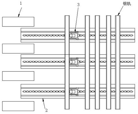
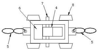
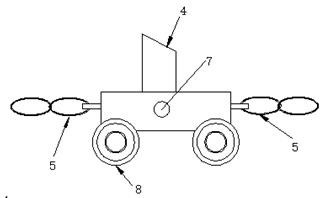
technical field [0001] The invention belongs to the technical field of rail transportation for operation transportation, and in particular relates to an automatic distribution and feeding mechanism for rails and a method thereof. Background technique [0002] During the production and manufacture of turnout rails, in order to facilitate the operation of workers and improve production efficiency, the processing machine tools will be equipped with special rail loading platforms. Rail loading platform (see figure 1 ) is mainly composed of a working roller table 1, a multi-group material rack 2 and a rail distribution feeding mechanism 3. Wherein, the rack 2 is mainly used to bear the weight of the rail. The rail distribution and feeding mechanism 3 is a chain transmission mechanism with a push block 4: (such as figure 2 , image 3 Shown) rail distribution feeding mechanism 3 is made up of push block 4, chain 5, block 6, bearing pin 7, roller 8. It is used to control the s...

Claims


Application Information

Patent Timeline
Patent Type & Authority Applications(China)
IPC IPC(8): B65G47/74
CPCB65G47/74
Inventor 薛喜丽卢德军吴钟敏刘江
Owner CHINA RAILWAY BAOQIAO (NANJING) CO LTD
Why Eureka
Try Eureka