
New energy power monitoring equipment

A power monitoring and new energy technology, applied in overhead line/cable equipment, TV, color TV, etc., can solve problems such as danger, damage and breakage, and achieve the effect of improving efficiency and safety

Active Publication Date: 2021-03-23
河南省同信电力工程有限公司
View PDF5 Cites 0 Cited by
  • Summary
  • Abstract
  • Description
  • Claims
  • Application Information

AI Technical Summary

Problems solved by technology

[0002] In the use of high-voltage lines in power engineering, because many high-voltage lines are in the wild natural environment, they are prone to damage and fracture due to the influence of the external harsh environment. This requires regular monitoring of high-voltage lines, and for some in steep mountainous areas, etc. It is dangerous to rely solely on manual inspection of high-voltage transmission lines. Therefore, how to monitor safety in real time and provide necessary reference data for centralized inspection and maintenance of electric power is very important.

Method used


Image

  • New energy power monitoring equipment
  • New energy power monitoring equipment
  • New energy power monitoring equipment

Examples


Embodiment Construction

[0020] The present invention is described in further detail below by embodiment, and embodiment is only used for illustrating the present invention, does not limit the scope of the present invention.

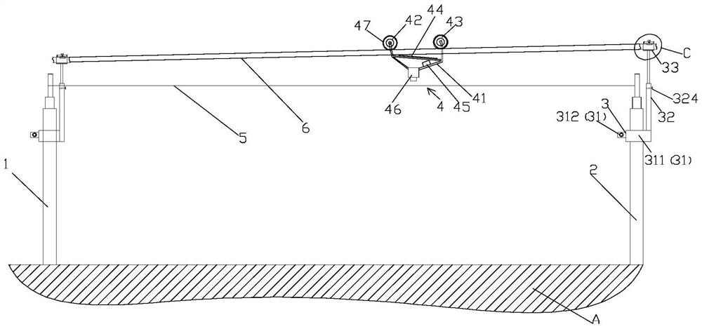
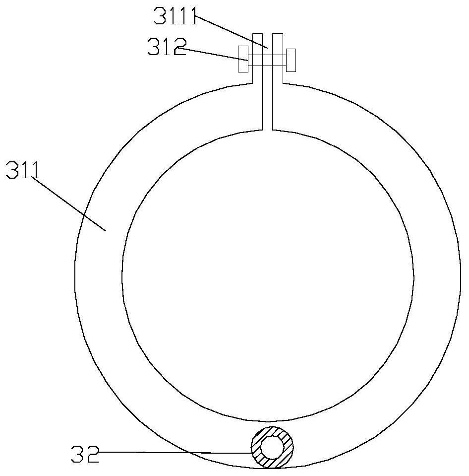
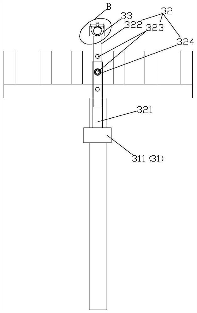
[0021] see Figure 1-5 The new energy power monitoring equipment shown includes a power support pole 1, a power support pole 2 2, a clamping component 3 and a monitoring component 4, and a power transmission line 5 is arranged between the power support pole 1 and the power support pole 2 Clamping assembly 3 is set on power support rod one 1 and power support rod two 2, guiding wire 6 is set between clamping components 3, monitoring assembly 4 is arranged on the upper part of guiding wire 6, guiding wire 6 is located at the upper part of transmission line 5 and monitoring assembly 4 is located at the top of the transmission line 5, and the height of the guide line 6 at the end 2 of the power support rod is greater than the height of the guide line 6 at the end 1 of the power supp...


PUM


Abstract

The invention belongs to the field of power monitoring equipment, and particularly relates to new energy power monitoring equipment. The equipment comprises a first electric power support rod, a second electric power support rod, clamping assemblies and a monitoring assembly, and is characterized in that a power transmission line is arranged between the first electric power support rod and the second electric power support rod, the clamping assemblies are arranged on the first electric power support rod and the second electric power support rod, a guide line is arranged between the clamping assemblies, and the monitoring assembly is arranged above the guide line; and the guide line is located at the upper part of the power transmission line, the monitoring assembly is located at the upperpart of the power transmission line, and the height of the guide line at end of the second electric power support rod is greater than the height of the guide line at the end of the first electric power support rod. According to the invention, manual work is replaced, the efficiency and safety of power transmission line monitoring are improved, the monitoring assembly is arranged on the guide linewhile the guide line is located on the upper part of the power transmission line, the power transmission line at the bottom of the guide line is monitored by controlling the monitoring assembly, and by utilizing the height difference of the guide line, the monitoring assembly can realize mobile monitoring without depending on the action of external force.

Description

technical field [0001] The invention belongs to the field of electric power monitoring equipment, and in particular relates to a new energy electric power monitoring equipment. Background technique [0002] In the use of high-voltage lines in power engineering, because many high-voltage lines are in the wild natural environment, they are prone to damage and fracture due to the influence of the external harsh environment. This requires regular monitoring of high-voltage lines, and for some in steep mountainous areas, etc. It is dangerous to rely solely on manual inspection of high-voltage transmission lines. Therefore, how to monitor safety in real time and provide necessary reference data for centralized inspection and maintenance of electric power is very important. Contents of the invention [0003] In order to solve the problems of the prior art, the invention provides a new energy power monitoring device. [0004] In order to achieve the above purpose, the present inv...

Claims


Application Information

Patent Timeline
IPC IPC(8): H02G1/02H02G7/00H04N5/225H04N7/18
CPCH02G1/02H02G7/00H04N7/18H04N23/57
Inventor 陈康危贵超万保林刘辉赵倩
Owner 河南省同信电力工程有限公司
Learn More