Die having cutting edge formed by plurality of blade elements

A technology of knives and components, applied in the field of knives, which can solve the problems of blade instability, arrangement structure and fastening cost, etc., and achieve the effect of simple repair and/or maintenance, short stop time, repair duration or repair duration

Active Publication Date: 2021-03-19
BAYERISCHE MOTOREN WERKE AG
View PDF11 Cites 0 Cited by
  • Summary
  • Abstract
  • Description
  • Claims
  • Application Information

AI Technical Summary

Problems solved by technology

[0004] This conventional arrangement and fastening of the blades has been particularly laborious due to the formation of the grooves in the blades
Furthermore, the blade has a reduced material thickness, especially in the region of the groove, on the corresponding groove-free part of the blade, so that the blade is particularly unstable at least in the region of the corresponding groove

Method used


Image

  • Die having cutting edge formed by plurality of blade elements
  • Die having cutting edge formed by plurality of blade elements

Examples


Embodiment Construction

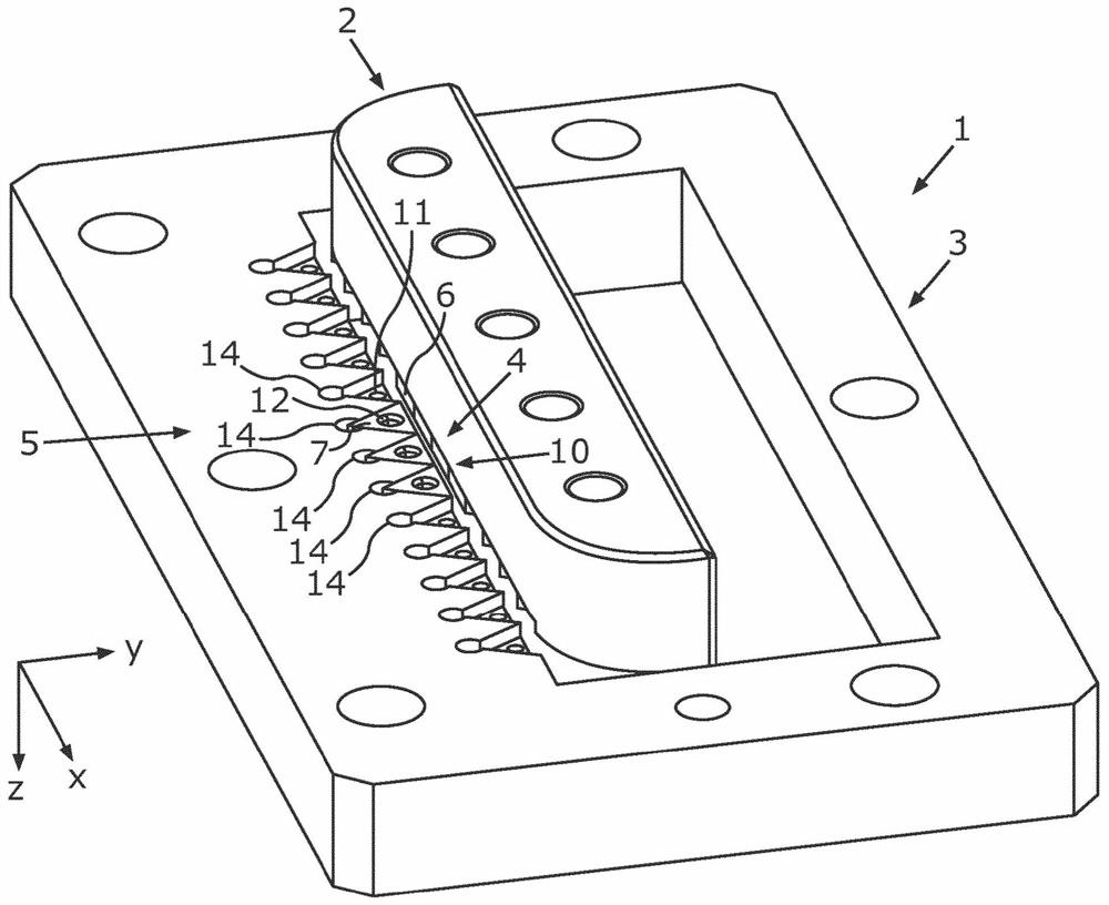
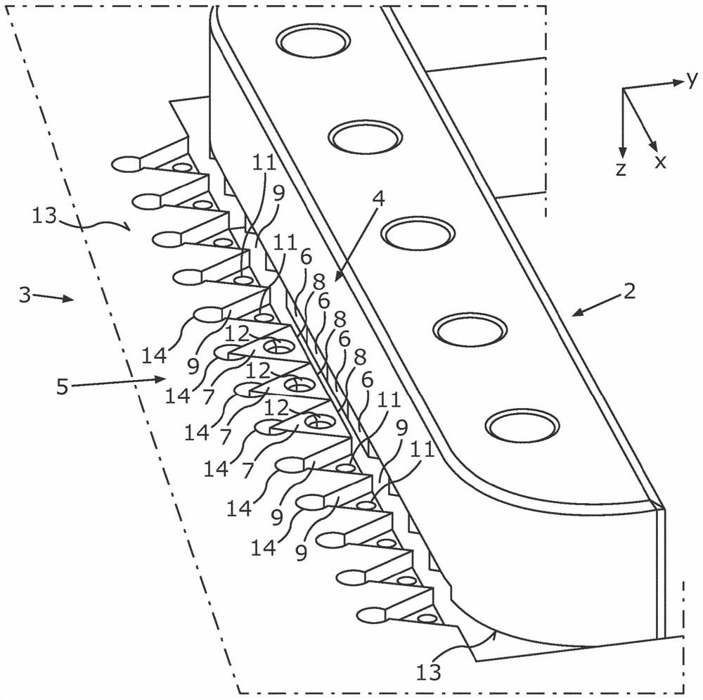
[0034] exist figure 1 schematically and in perspective and in figure 2 The tool 1 shown in more detail in FIG. 1 is provided for cutting workpieces, in particular metal workpieces, and has a first tool part 2 and a second tool part 3 . The first knife part 2 has a first cutting edge 4 and the second knife part 3 has a second cutting edge 5 . For cutting, for example cutting and / or breaking off a workpiece, the tool 1 or the tool parts 2, 3 can be adjusted into an open position in which it is possible to arrange, for example, between the two tool parts 2, 3 Put in the workpiece. For example, the workpiece to be cut can be a sheet-shaped shaped metal body, for example a metal sheet, a coil or the like. If the workpiece is arranged between the tool parts 3, 4 or between the cutting edges 4, 5, the tool parts 2, 3 can be moved towards each other from the open position into the breaking position, whereby the cutting edges 4, 5 first plastically deform the workpiece and Finally...


PUM


Abstract

The invention relates to a die (1) for cutting a workpiece. The die (1) comprises a first die part (2), which has a first cutting edge (4) formed by a plurality of first blade elements (6), and comprises a second die part (3) which is opposite to the first die part (2) and has a second cutting edge (5), wherein, in order to cut the workpiece which can be arranged between the die parts (2, 3), thedie parts (2, 3) can be moved towards one another from an open position into a cutting position. According to the invention, a particular, separated receiving contour (9) of the first die part (2) isassociated with the relevant first blade element (6), wherein the receiving contour corresponds to a particular external contour of the relevant first blade element (6), and the relevant first blade element (6) is form-fittingly arranged at least predominantly in the associated receiving contour (9) of the first die part (2).

Description

technical field [0001] The invention relates to a tool for cutting a workpiece having the features of claim 1 . Background technique [0002] During the production, especially the mass production, of motor vehicles, shear cutting or stamping is used today in order to produce sheet metal shaped parts, in particular body parts. By means of shear cutting, it is possible to separate (cut out, perforate) cut parts from the sheet metal and / or separate (cut off) waste material from the sheet metal. Usually, a pressure-integrated cutting tool is used for this purpose, which has one cutting knife or two cutting knives located opposite one another, the blades of which are ground and hardened. When the cutting edge or blade wears, it is therefore necessary to replace it completely or to weld material onto the worn area of ​​the blade and then to remove material, in particular to sharpen the corresponding blade by means of grinding. On the one hand, this requires a particularly high e...

Claims


Application Information

Patent Timeline
Patent Type & Authority Applications(China)
IPC IPC(8): B23D35/00B21D28/02
CPCB23D35/001B23D35/002B21D28/02B21D28/14B21D37/00
Inventor R·林达歇尔R·基施纳B·贝维克D·奥佩尔
Owner BAYERISCHE MOTOREN WERKE AG
Why Eureka
Try Eureka