Multi-stage air supply control method for wall-mounted air conditioner

A technology of wall-mounted air conditioner and control method, which is applied in space heating and ventilation control input, heating and ventilation control system, control input related to air characteristics, etc. Leaf and other issues to achieve the effect of improving user experience

Active Publication Date: 2021-03-19
四川长虹空调有限公司
View PDF17 Cites 5 Cited by
  • Summary
  • Abstract
  • Description
  • Claims
  • Application Information

AI Technical Summary

Problems solved by technology

[0002] At present, the existing wall-mounted air conditioners have relatively simple indoor air supply methods, usually at a fixed angle and in a fixed manner, requiring users to manually adjust the angle of swing blades and wind speed, and the operation is cumbersome; according to market feedback, when a large number of users actually use the air conditioner There is a phenomenon of manually adjusting the swing blade and wind speed, and the user experience is poor

Method used


Image

  • Multi-stage air supply control method for wall-mounted air conditioner
  • Multi-stage air supply control method for wall-mounted air conditioner

Examples


Embodiment 1

[0031] In this embodiment, the multi-stage air supply control process is described by taking the air conditioner working in the cooling mode as an example.

[0032] Such as figure 1 As shown, it includes the following steps:

[0033] S1. Obtain the first temperature difference T1 between the indoor real-time ambient temperature and the set temperature; that is, T1=indoor real-time ambient temperature-set temperature;

[0034] S2. Determine whether the first temperature difference value T1 is greater than the first preset value, if so, adjust the speed of the internal fan to run at a high speed, and adjust the swing blade angle to the maximum range to sweep the wind; otherwise, go to step S3;

[0035] In this step, the first preset value is selected according to the actual system. Taking the 35-unit product as an example, it can be selected as 3. At this stage, the high speed of the fan and the large opening of the swing blade can ensure the rapid cooling of the room;

[0036...

Embodiment 2

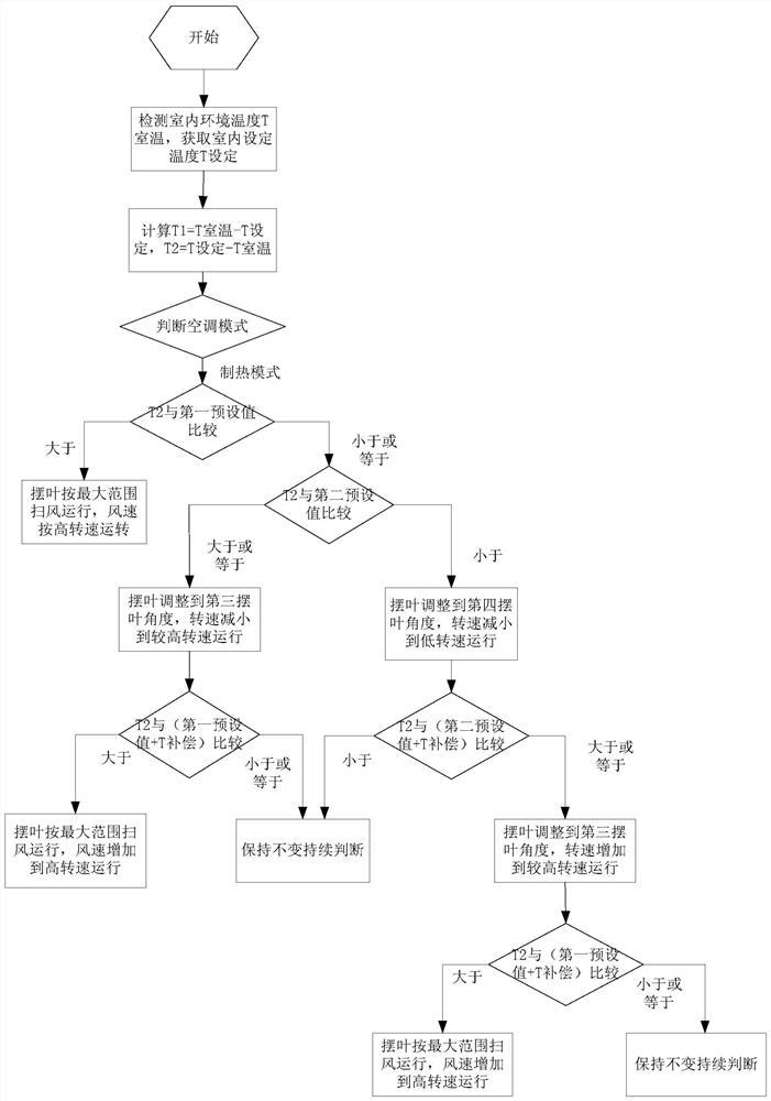
[0042] In this embodiment, the multi-stage air supply control process is described by taking the air conditioner working in the heating mode as an example.

[0043] Such as figure 2 As shown, it includes the following steps:

[0044] S1. Obtain the second temperature difference T2 between the set temperature and the real-time indoor ambient temperature; that is, T2=set temperature-indoor real-time ambient temperature;

[0045] S2. Determine whether the second temperature difference T2 is greater than the first preset value, if so, adjust the speed of the internal fan to run at a high speed, and adjust the swing blade angle to the maximum range to sweep the wind; otherwise, go to step S3;

[0046] In this step, the first preset value is selected according to the actual system. Taking the 35-unit product as an example, it can be selected as 3. At this stage, the high speed of the fan and the large opening of the swing blade can ensure the rapid temperature rise of the room. C...


PUM


Abstract

The invention relates to the technical field of air conditioners, and discloses a multi-stage air supply control method for a wall-mounted air conditioner. According to the multi-stage air supply control method, automatic judgment of load is achieved, automatic adjustment of swing blade angle and air speed is achieved, and user experience is improved. The multi-stage air supply control method forthe wall-mounted air conditioner comprises the steps that in a refrigeration mode, the rotating speed of an inner draught fan and / or the swing blade angle are / is automatically controlled to operate ina corresponding state according to the size relation between a temperature difference value of the indoor real-time environment temperature and the set temperature and different temperature thresholds; and in the heating mode, the rotating speed of the inner draught fan and / or the swing blade angle are / is automatically controlled to operate in the corresponding state according to the size relation between the temperature difference value of the set temperature and the indoor real-time environment temperature and the different temperature thresholds.

Description

technical field [0001] The invention relates to the technical field of air conditioners, in particular to a multi-stage air supply control method for a wall-mounted air conditioner. Background technique [0002] At present, the existing wall-mounted air conditioners have a relatively simple indoor air supply method, usually at a fixed angle and in a fixed manner, requiring users to manually adjust the swing blade angle and wind speed, and the operation is cumbersome; according to market feedback, when a large number of users actually use the air conditioner There is a phenomenon of manually adjusting the swing blade and wind speed, and the user experience is poor. Contents of the invention [0003] The technical problem to be solved by the present invention is to propose a multi-stage air supply control method for a wall-mounted air conditioner, which can automatically judge the load, automatically adjust the swing blade angle and wind speed, and improve user experience. ...

Claims


Application Information

Patent Timeline
Patent Type & Authority Applications(China)
IPC IPC(8): F24F11/64F24F11/67F24F11/77F24F11/79F24F110/10
CPCF24F11/64F24F11/67F24F11/77F24F11/79F24F2110/10Y02B30/70
Inventor 赵一麟李峰余豹谢鹏
Owner 四川长虹空调有限公司
Why Eureka
Try Eureka