
Faucet with water diversion function

A faucet and function technology, applied in the field of faucets, can solve the problems of laborious pulling rod caps, sliding wire rod caps falling off, fast aging speed of sealing rings, etc., achieving the effect of simple and convenient operation and convenient replacement.

Pending Publication Date: 2021-03-19
徐成业
View PDF0 Cites 0 Cited by
  • Summary
  • Abstract
  • Description
  • Claims
  • Application Information

AI Technical Summary

Problems solved by technology

[0002] At present, the faucet usually uses a pull-rod water separator to realize the water diversion function. The pull-rod water separator includes a pull rod, a pull rod cap threaded on one end of the pull rod and a sealing ring connected to the other end of the pull rod; the pull rod cap drives the seal through the pull rod. The circle moves, so as to control the water flow to the outlet of the water distributor or to the outlet of the faucet to realize water diversion; however, in the daily use of the rod-type water separator, it is laborious for the user to pull the rod cap, and due to the gap between the rod cap and the rod The threaded connection is easy to cause slippage and cause the rod cap to fall off; moreover, the sealing ring in the rod type water separator ages quickly, and the aging of the sealing ring will lead to abnormal water discharge

Method used


Image

  • Faucet with water diversion function
  • Faucet with water diversion function
  • Faucet with water diversion function

Examples


Embodiment Construction

[0024] In order to make the object, technical solution and advantages of the present invention clearer, the present invention will be further described in detail below in conjunction with the accompanying drawings and embodiments. It should be understood that the specific embodiments described here are only used to explain the present invention, not to limit the present invention.

[0025] The specific implementation of the present invention will be described in detail below in conjunction with specific embodiments.

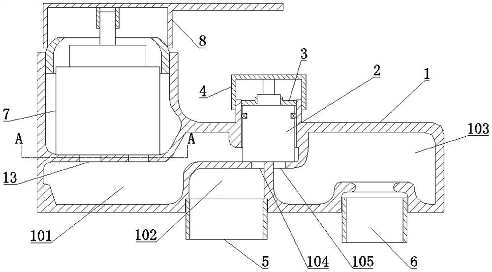
[0026] Such as figure 1 As shown, it is a schematic structural diagram of a faucet with a water diversion function provided by an embodiment of the present invention, including:

[0027] The housing 1 is provided with a water inlet chamber 101, a first water outlet chamber 102, and a second water outlet chamber 103 inside;

[0028] The water diversion valve 2 is detachably installed in the water inlet chamber 101;

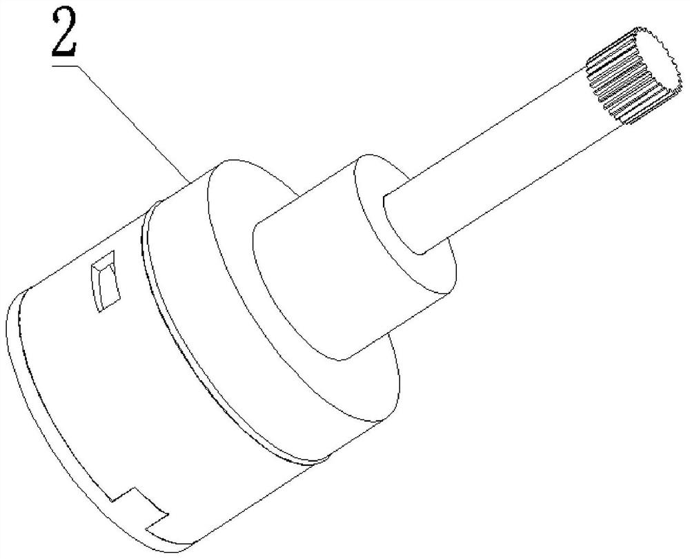
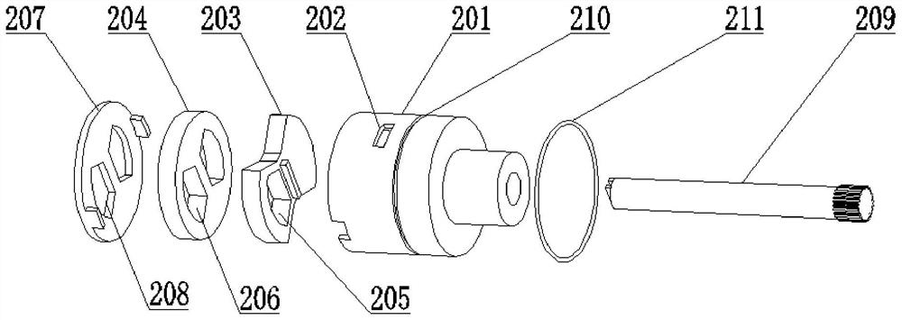
[0029] Among them, such as figure 2 and ...


PUM


Abstract

The invention is applicable to the technical field of faucets, and provides a faucet with a water diversion function, which comprises a shell, and a water inlet cavity, a first water outlet cavity anda second water outlet cavity are arranged in the shell; a water diversion valve comprising a valve sleeve, a first water diversion sheet, a second water diversion sheet, a bottom cover and a rotatingshaft; the water division valve is mounted in the water inlet cavity through the bottom cover mounted at one end of the valve sleeve; a plurality of water inlets and a first sealing ring are arrangedon the valve sleeve; the second water diversion sheet is arranged in the valve sleeve, and the two sides of the second water diversion sheet are attached to the bottom cover and the first water diversion sheet respectively; two second through holes are formed on the second water diversion sheet, and two third through holes communicated with the second through holes are formed on the bottom cover;a first through hole is formed on the first water diversion sheet; one end of the rotating shaft is connected with the first water division sheet, and the other end of the rotating shaft is connectedwith a rotating piece; and the two third through holes are respectively communicated with the first water outlet cavity and the second water outlet cavity through a first communication hole and a second communication hole on a water division valve mounting surface. The embodiment of the invention is simple and convenient to operate, and does not cause abnormal water outlet.

Description

technical field [0001] The invention belongs to the technical field of faucets, in particular to a faucet with a water diversion function. Background technique [0002] At present, the faucet usually uses a pull-rod water separator to realize the water diversion function. The pull-rod water separator includes a pull rod, a pull cap threaded on one end of the pull rod, and a sealing ring connected to the other end of the pull rod; the pull rod cap drives the seal through the pull rod. The ring moves to control the water flow to the outlet of the water distributor or to the outlet of the faucet to realize water diversion; however, in daily use of the rod-type water separator, it is laborious for the user to pull the rod cap, and due to the gap between the rod cap and the rod The threaded connection is easy to cause slippage and cause the rod cap to fall off; moreover, the sealing ring in the rod type water separator ages quickly, and the aging of the sealing ring will lead to ...

Claims


Application Information

Patent Timeline
IPC IPC(8): F16K11/22F16K27/04F16K31/60
CPCF16K11/22F16K27/045F16K31/60
Inventor 不公告发明人
Owner 徐成业
Learn More