Vertical water purification equipment

A water purification equipment and vertical technology, applied in the field of vertical water purification equipment, can solve problems such as inability to receive water, and achieve the effects of accurate water connection, accuracy, and prevention of being scalded.

Inactive Publication Date: 2021-03-19
江苏全给净化科技有限公司
View PDF3 Cites 0 Cited by
  • Summary
  • Abstract
  • Description
  • Claims
  • Application Information

AI Technical Summary

Problems solved by technology

[0007] The purpose of the present invention is to provide a vertical water purification device to solve the problem in the above-mentioned background technology that it is not convenient to place and receive water according to the length of the cup body, resulting in the inability of some long cups to receive water

Method used


Image

  • Vertical water purification equipment
  • Vertical water purification equipment
  • Vertical water purification equipment

Examples


Embodiment 1

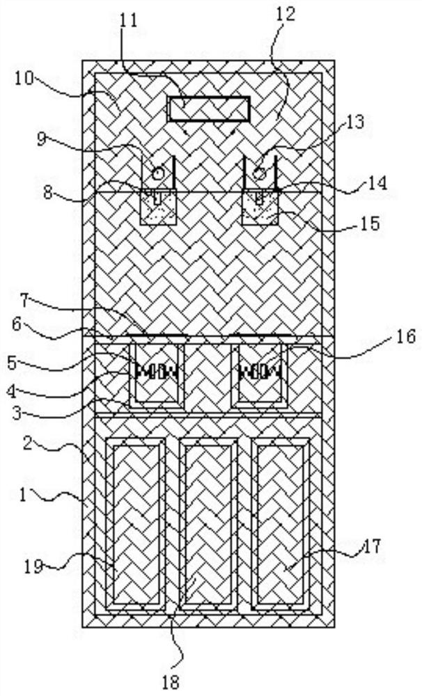
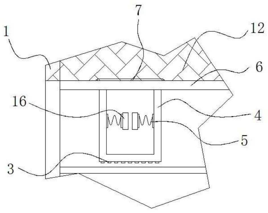
[0025] Example 1: See Figure 1-4 , a vertical water purification device, comprising a cabinet body 1 and a lower cabinet door 2, one end of the cabinet body 1 is movably hinged with a lower cabinet door 2, and the cabinet body 1 at the top of the lower cabinet door 2 is movably hinged with an upper cabinet door 12, The inside of the top of the cabinet 1 is fixedly connected with a housing 10, and one end of the housing 10 is provided with a display screen 11, and one end of the cabinet 1 at the bottom of the display screen 11 is provided with a hot water button 9, and the housing on one side of the hot water button 9 The body 10 is provided with a cold water button 13, the bottom end of the housing 10 is fixedly connected with a hot water outlet 8, and the bottom end of the housing 10 on one side of the hot water outlet 8 is fixedly connected with a cold water outlet 14, hot water outlet 8 and cold water outlet 14 One end of the cabinet is provided with a splash-proof structu...

Embodiment 2

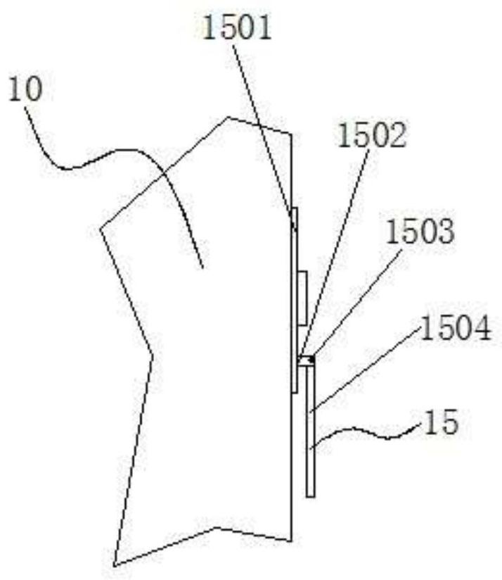
[0031] Embodiment 2: The splash-proof structure 15 is composed of a chute 1501, a movable block 1502, a hinge shaft 1503 and a splash-proof plate 1504. The chute 1501 is respectively arranged inside one end of the casing 10 on both sides of the hot water button 9 and the cold water button 13, The inside of the chute 1501 is provided with a movable block 1502, and one side of the movable block 1502 is fixedly connected with a hinge shaft 1503, and the outside of the hinge shaft 1503 is hinged with a splash guard 1504;

[0032] The movable block 1502 is embedded inside the chute 1501, a sliding structure is formed between the movable block 1502 and the chute 1501, and the splash guard 1504 is made of transparent material;

[0033] Specifically, as figure 1 and figure 2 As shown, when receiving water, the splash guard 1504 can be slid down through the movable block 1502, and the splash guard 1504 can be adjusted by using the movable hinge relationship between the splash guard 1...


PUM


Abstract

The invention discloses vertical water purification equipment, and particularly relates to the technical field of vertical water purification equipment. The vertical water purification equipment comprises a cabinet body and a lower cabinet door, wherein the lower cabinet door is movably hinged to one end of the cabinet body, an upper cabinet door is movably hinged to the cabinet body at the top end of the lower cabinet door, a shell is fixedly connected to the interior of the top end of the cabinet body, and a display screen is arranged at one end of the shell; a hot water button is arranged at one end of the cabinet body at the bottom end of the display screen, a cold water button is arranged on the shell on one side of the hot water button, and a hot water outlet is fixedly connected tothe bottom end of the shell. Herein, the auxiliary placement structure comprises the water receiving plate, the placement groove, the drainage holes and the cover plate; since the placement groove isfixedly connected to the bottom of the water receiving plate, a cup with a long cup body can be placed in the placement groove to receive water; and when the cup with a short cup body receives water,the cover plate can be turned over to the water receiving plate and placed above the water receiving plate; therefore, the cup can be placed and used for receiving water according to the length of thecup body, and the equipment is better in application effect.

Description

technical field [0001] The invention relates to the technical field of vertical water purification equipment, in particular to a vertical water purification equipment. Background technique [0002] With the development of life, people have higher and higher requirements for the quality of water sources. Water purifiers have gradually entered people's lives. Water purifiers are a kind of equipment for advanced treatment of tap water. Drinking directly is more hygienic. The existing water purification equipment still has some problems in design, which makes it not suitable for use. Therefore, we need to improve a vertical water purification equipment. [0003] In the process of realizing the present invention, the inventors have found that at least the following problems in the prior art have not been resolved: [0004] (1) The traditional vertical water purification equipment is not convenient for placing and receiving water according to the length of the cup body, resulting...

Claims


Application Information

Patent Timeline
Patent Type & Authority Applications(China)
IPC IPC(8): C02F9/02B01D24/00B01D24/10A47J31/00A47J31/44A47J31/46A47J31/60
CPCC02F1/001C02F1/283B01D24/007B01D24/10A47J31/00A47J31/44A47J31/46A47J31/60
Inventor 王中有王智博
Owner 江苏全给净化科技有限公司
Why Eureka
Try Eureka