
Tool display rack and subway electric power overhaul vehicle thereof

A technology for display racks and tools, which is applied to trolleys, motor vehicles, multi-axis trolleys, etc., can solve the problems of inconvenient use, difficult placement, heavy tools, etc., and achieve the effect of convenient use and increased stability

Active Publication Date: 2021-03-19
CHONGQING VOCATIONAL INST OF ENG
View PDF18 Cites 1 Cited by
  • Summary
  • Abstract
  • Description
  • Claims
  • Application Information

AI Technical Summary

Problems solved by technology

[0009] The purpose of the present invention is to provide a subway electric maintenance car and its tool display rack. The tool display rack can solve the problem that when the existing maintenance tools are placed on the display rack, some tools are heavy and difficult to be placed on the display rack. Disadvantages of high position, which leads to inconvenient use

Method used


Image

  • Tool display rack and subway electric power overhaul vehicle thereof
  • Tool display rack and subway electric power overhaul vehicle thereof
  • Tool display rack and subway electric power overhaul vehicle thereof

Examples


Embodiment 1

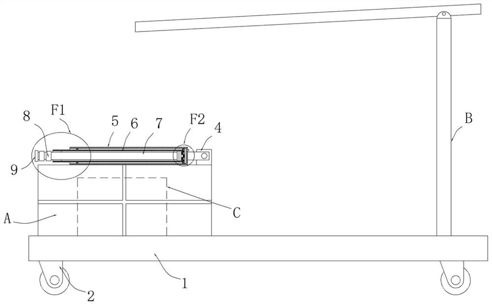
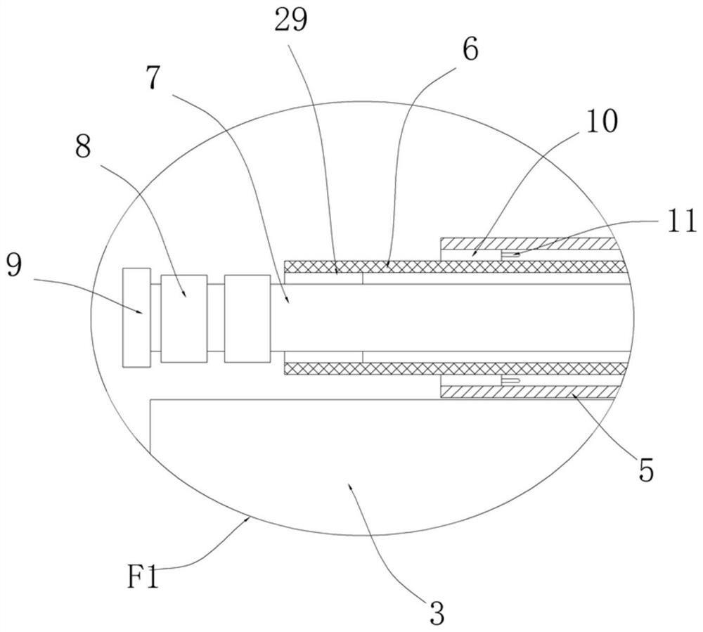
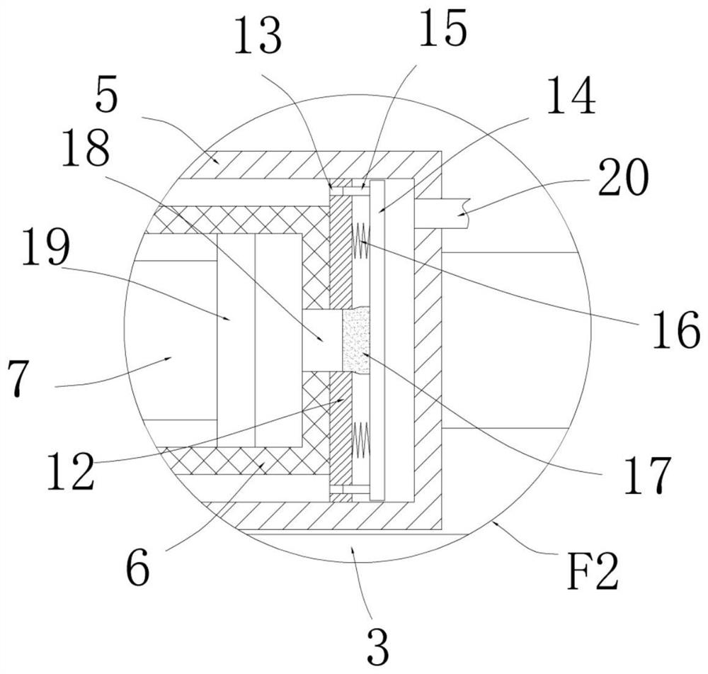
[0054] refer to Figure 1-5 , the adjustable ladder structure of the present embodiment includes a car board 1, a tool display rack A is installed on the top of the car board 1, four universal wheels 2 are arranged on the bottom of the car board 1, and a motor is installed on the top of the tool display rack A Structure 4, two first support cylinders 5 are connected to the motor structure 4, the second support cylinder 6 is slidably installed in the two first support cylinders 5, and the ladder rod 7 is slidably installed in the two second support cylinders 6 The outer sides of the two first support cylinders 5, the two second support cylinders 6 and the two ladder rods 7 are movably connected with collars 8, and the bottom ends of the two first support cylinders 5 are provided with the same bottom bar 21, Outrigger rods 22 are connected between the two first support cylinders 5, the two second support cylinders 6 and the two ladder rods 7, and a collar 8 is arranged on the ou...

Embodiment 2

[0062] refer to Figure 1-5 , the adjustable ladder structure of the present embodiment includes a car board 1, a tool display rack A is installed on the top of the car board 1, four universal wheels 2 are arranged on the bottom of the car board 1, and a motor is installed on the top of the tool display rack A Structure 4, two first support cylinders 5 are connected to the motor structure 4, the motor structure 4 includes a motor, a rotating shaft and a bracket, the bracket plays a supporting role, the rotating shaft is rotated and installed on the bracket, the motor is connected to the rotating shaft, two The first support cylinders 5 are all fixedly installed with the rotating shaft, and the motor can drive the two first support cylinders 5 to rotate through the rotating shaft to adjust the angle. The second support cylinder 6 is slidingly installed in the two first support cylinders 5. A ladder rod 7 is slidably installed in each of the second support cylinders 6, and a col...

Embodiment 3

[0071] refer to Figure 6-9 , the tool display rack of this embodiment includes a frame base A1, which is installed on the vehicle plate 1, and two symmetrically arranged frame support plates A2 are fixedly installed on the top of the frame base A1, and the two frame bodies The top of the support plate A2 is fixedly installed with the same frame body top plate A4, between the two frame body support plates A2 is fixedly installed with a plurality of frame body laminates A3, and the top of the frame body top plate A4 is fixedly installed with the first frame body motor A6 There are two symmetrically arranged frame threaded rods A5 connected in rotation between the frame top plate A4 and the frame base A1, the two frame body threaded rods A5 are connected by transmission, and the frame threaded rod A5 is threadedly connected with a frame moving seat A7 , the two frame moving seats A7 are rotated and connected with two symmetrically arranged frame placement rods A8, the two frame ...


PUM


Abstract

The invention discloses a tool display rack and a subway electric power overhaul vehicle thereof, and aims to solve the problems that when existing overhaul tools are placed on the display stand, sometools are heavy and are difficult to place at high positions on the display stand, so that the existing overhaul tools are inconvenient to use. The rack comprises a rack body base, two symmetrically-arranged frame body supporting plates are fixedly installed at the top of the rack body base, the same rack body top plate is fixedly installed at the tops of the two rack body supporting plates, a plurality of rack body layer plates are fixedly installed between the two rack body supporting plates, and a first rack body motor is fixedly installed at the top of the rack body top plate; and two symmetrically-arranged rack body threaded rods are rotatably connected between the rack body top plate and the rack body base, the two rack body threaded rods are in transmission connection, rack body moving seats are in threaded connection with the rack body threaded rods, and two symmetrically-arranged rack body placing rods are rotatably connected between the two rack body moving seats. The rack is easy to operate and convenient to use, heavy tools can be conveniently placed on the rack body laminate at the high position, and people can use the rack conveniently.

Description

technical field [0001] The invention relates to the field of subway maintenance, in particular to a subway electric maintenance vehicle. Background technique [0002] Subway is a form of railway transportation, which refers to the urban rail transit system that mainly operates underground, that is, the abbreviation of "underground railway" or "underground railway". Many such systems are designed to match the built environment and consider construction and operating costs May turn into surface or elevated sections outside urban centers. The subway is an urban rail transit system that covers various underground and above-ground right-of-way exclusive, high-density, and high-capacity urban rail transit systems in urban areas. The Taiwan Metro of China is called "MRT". In the process of electric power construction, manual operations are required in many places, especially some electric maintenance personnel are required to overhaul circuits or electric equipment. At present, th...

Claims


Application Information

Patent Timeline
Patent Type & Authority Applications(China)
IPC IPC(8): B62B3/02B62B3/04B62B5/00B62B5/04E06C5/12E06C5/42B66F11/04
CPCB62B3/02B62B3/04B62B5/0433B62B5/0485B62B5/00E06C5/12E06C5/42B66F11/04B62B2203/07B62B2203/10B62B2203/70
Inventor 孙文杰
Owner CHONGQING VOCATIONAL INST OF ENG
Learn More