
Gravel vibration feeding equipment

A vibrating feeding and equipment technology, applied in vibrating conveyors, conveyor objects, loading/unloading, etc., can solve the problems of multiple manpower and material resources, volume and weight, etc., to enhance work efficiency, improve work stability, and improve work tidiness sexual effect

Pending Publication Date: 2021-03-16
临澧县步印新型墙体材料有限公司
View PDF0 Cites 1 Cited by
  • Summary
  • Abstract
  • Description
  • Claims
  • Application Information

AI Technical Summary

Problems solved by technology

, the structure of the existing vibrating feeder is relatively heavy. When the feeding direction of the vibrating feeder needs to be changed due to feeding requirements, multiple staff and even other auxiliary machinery vehicles are often required to switch the feeding direction of the vibrating feeder. The material direction consumes more manpower and material resources. Therefore, an improved technology is urgently needed to solve this problem existing in the prior art.

Method used


Image

  • Gravel vibration feeding equipment
  • Gravel vibration feeding equipment
  • Gravel vibration feeding equipment

Examples


Embodiment Construction

[0018] The following will clearly and completely describe the technical solutions in the embodiments of the present invention with reference to the accompanying drawings in the embodiments of the present invention. Obviously, the described embodiments are only some, not all, embodiments of the present invention. Based on the embodiments of the present invention, all other embodiments obtained by persons of ordinary skill in the art without making creative efforts belong to the protection scope of the present invention.

[0019] In the description of the present invention, it should be noted that the terms "upper", "lower", "inner", "outer", "front end", "rear end", "both ends", "one end", "another end" The orientation or positional relationship indicated by etc. is based on the orientation or positional relationship shown in the drawings, and is only for the convenience of describing the present invention and simplifying the description, rather than indicating or implying that ...


PUM


Abstract

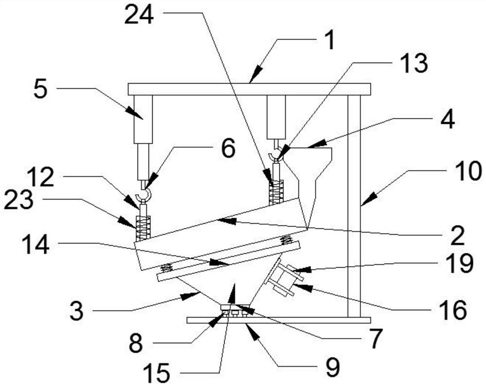
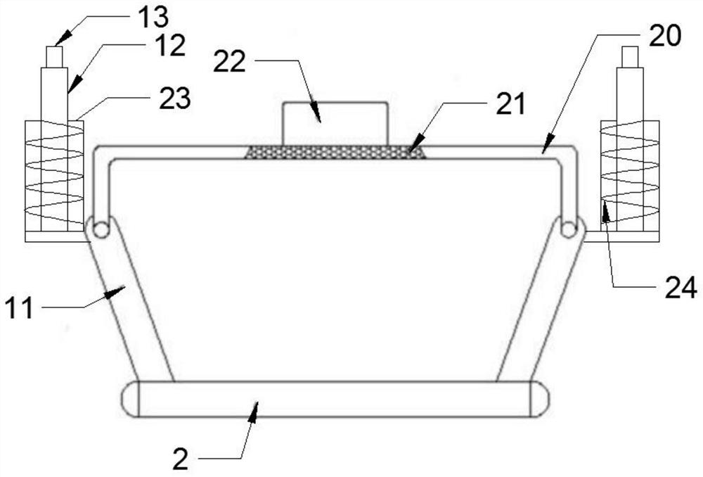
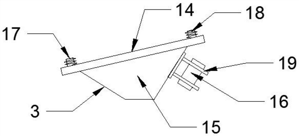
The invention discloses gravel vibration feeding equipment. The equipment comprises a fixing frame, a feeding groove and a vibration device, a feeding bin is welded to one end of the feeding groove, electric telescopic rods are fixedly connected to the positions, corresponding to the two ends of the feeding groove, of the lower end of the fixing frame, lifting hooks are fixedly connected to the lower ends of the electric telescopic rods, and the lower ends of the lifting hooks are connected with the feeding groove. A vibration device is connected to the lower end of the feeding groove, a baseplate is welded to the lower portion of the vibration device, the lower surface of the base plate is elastically connected with a supporting plate through evenly-distributed damping balls, and one side of the upper surface of the supporting plate is connected with a fixing frame through a first supporting rod. According to the vibrating feeding equipment, a dustproof cover is arranged to achieve the dustproof protection effect on sand and stone in the feeding groove, the phenomenon that dust drifts around in the sand and stone feeding process is prevented, and meanwhile the working cleanlinessof the vibrating feeding equipment is improved through cooperation with an exhaust fan.

Description

technical field [0001] The invention relates to the technical field of vibrating feeding equipment, in particular to vibrating feeding equipment for sand and gravel. Background technique [0002] Feeding equipment is an auxiliary equipment in the mechanized storage and transportation system of lime production enterprises. Its main function is to continuously and evenly feed processed or unprocessed materials from a certain equipment (hopper, storage bin, etc.) To undertake equipment or transport machinery. The vibrating feeder used in mines is used to uniformly or quantitatively supply materials from storage bins or other storage equipment to receiving equipment, and is an essential equipment for the automation of assembly line operations. , the structure of the existing vibrating feeder is relatively heavy. When the feeding direction of the vibrating feeder needs to be changed due to feeding requirements, multiple staff and even other auxiliary machinery vehicles are often...

Claims


Application Information

Patent Timeline
IPC IPC(8): B65G27/04B65G27/08B65G41/00B65G69/18B65G27/16
CPCB65G27/04B65G27/08B65G27/16B65G41/00B65G69/186B65G2201/045
Inventor 何少华
Owner 临澧县步印新型墙体材料有限公司
Learn More