CO2 laser cutting equipment for Mini LED backlight production and cutting method

A laser cutting and laser cutting machine technology, applied in laser welding equipment, welding equipment, metal processing equipment, etc., can solve the problems of wasting cutting time and time for picking and placing materials, inconvenient rotation of the cutting platform, and high labor intensity of workers. To achieve the effect of balancing the time of picking and placing materials, low maintenance cost and convenient control

Active Publication Date: 2021-03-16
珠海市科弥光电有限公司
View PDF6 Cites 0 Cited by
  • Summary
  • Abstract
  • Description
  • Claims
  • Application Information

AI Technical Summary

Problems solved by technology

[0005] The purpose of the present invention is to provide a CO2 laser cutting equipment and cutting method for Mini LED backlight production, which can realize the alternate operation of fixing the light guide plate and rotating the light guide plate to directly below the laser cutting head through a single driving part, without requiring many One driving part, more convenient control, convenient maintenance and low maintenance cost, solve the problem that the cutting platform in the existing backlight laser cutting machine is not easy to rotate, thus wasting the cutting time and the time of picking and placing materials, resulting in low work efficiency , the problem of high labor intensity of workers

Method used


Image

  • CO2 laser cutting equipment for Mini LED backlight production and cutting method
  • CO2 laser cutting equipment for Mini LED backlight production and cutting method
  • CO2 laser cutting equipment for Mini LED backlight production and cutting method

Examples


Embodiment Construction

[0030] The following will clearly and completely describe the technical solutions in the embodiments of the present invention with reference to the accompanying drawings in the embodiments of the present invention. Obviously, the described embodiments are only some, not all, embodiments of the present invention. Based on the embodiments of the present invention, all other embodiments obtained by persons of ordinary skill in the art without making creative efforts belong to the protection scope of the present invention.

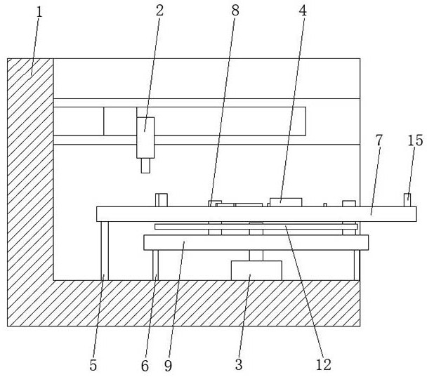
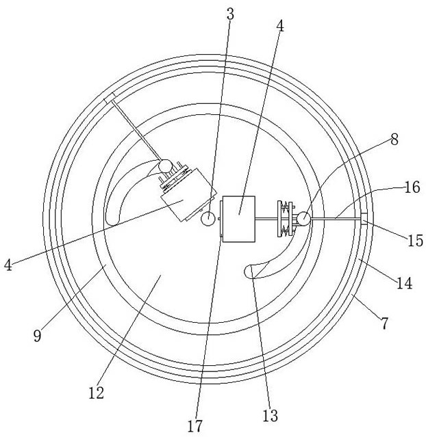
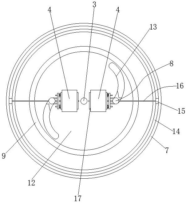
[0031] see Figure 1 to Figure 6 , the present invention provides a technical solution: a CO2 laser cutting equipment for Mini LED backlight production, including a laser cutting machine main body 1 and a laser cutting head 2, the surface of the laser cutting machine main body 1 is provided with a rotating drive source 3, and also includes Two transmission mechanisms, through the operation of the driving part of the rotating drive source 3, and under the actio...


PUM


Abstract

The invention discloses CO2 laser cutting equipment for Mini LED backlight production and a cutting method, and relates to the technical field of LED backlight source cutting. The CO2 laser cutting equipment comprises a laser cutting machine body and a laser cutting head, and a rotary driving source is arranged on the surface of the laser cutting machine body. The CO2 laser cutting equipment further comprises two transmission mechanisms. Through the operation of a driving part of the rotary driving source, and under the action of the two transmission mechanisms, two light guide plates are alternately fixed, and the two light guide plates are alternately rotated to the position under the laser cutting head. The CO2 laser cutting equipment has the effects that the light guide plates can be fixed and rotated to the position under the laser cutting head through the single driving part to alternately operate, multiple driving parts are not needed, control is more convenient, maintenance isconvenient, and the maintenance cost is low. The problems that a cutting platform in an existing backlight source laser cutting machine is inconvenient to rotate, and therefore, cutting time and material taking and placing time are wasted, the working efficiency is made low and the labor intensity of workers is high are solved.

Description

technical field [0001] The invention relates to the technical field of LED backlight cutting, in particular to CO2 laser cutting equipment and a cutting method for Mini LED backlight production. Background technique [0002] With the rise and maturity of organic light-emitting diode (OLED, Organic Light-Emitting Diode) technology, OLED products have gradually become the new favorite in the market. Relatively speaking, thin film transistor liquid crystal display (TFT-LCD, ThinFilm TransistorLiquid Crystal Display) is There is a certain gap in performance compared with OLED technology. In order to better improve the display performance of LCD, especially in the field of contrast to catch up with OLED technology, while retaining the price and reliability advantages of LCD, Mini LED backlight came into being, using local backlight adjustment (Localdimming), a regional control Optical technology, controlling the 8K LCD panel with MiniLED backlight, will be the strongest spear fo...

Claims


Application Information

Patent Timeline
Patent Type & Authority Applications(China)
IPC IPC(8): B23K26/08B23K26/12B23K26/38B23K26/70
CPCB23K26/123B23K26/38B23K26/0869B23K26/702
Inventor 刘礼龙刘炫言
Owner 珠海市科弥光电有限公司
Why Eureka
Try Eureka