Detection mechanism and mower

A lawn mower and a technology for detecting signals, applied in the field of detection mechanism and lawn mower

Pending Publication Date: 2021-03-12
CHANGZHOU GLOBE CO LTD
View PDF0 Cites 3 Cited by
  • Summary
  • Abstract
  • Description
  • Claims
  • Application Information

AI Technical Summary

Problems solved by technology

[0003] The currently widely used sensor is a magnet-Hall combination. When the device is started, the relative position between the magnet and the Hall needs to be in a triggered state. It is generally used to detect the static position between the magnet and the Hall. There are certain disadvantages in the detection of collision process and collision direction

Method used


Image

  • Detection mechanism and mower
  • Detection mechanism and mower
  • Detection mechanism and mower

Examples


Embodiment Construction

[0029] In order to make the object, technical solution and advantages of the present invention clearer, the present invention will be described in detail below in conjunction with the accompanying drawings and specific embodiments.

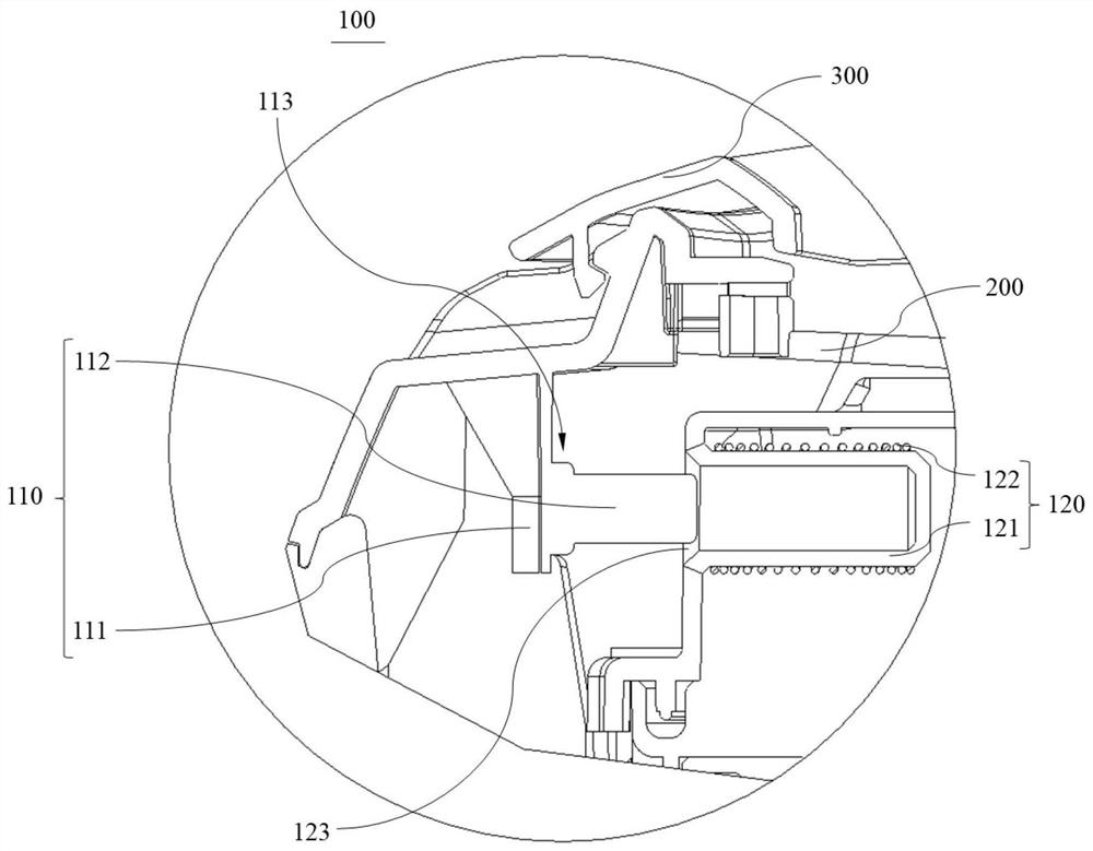
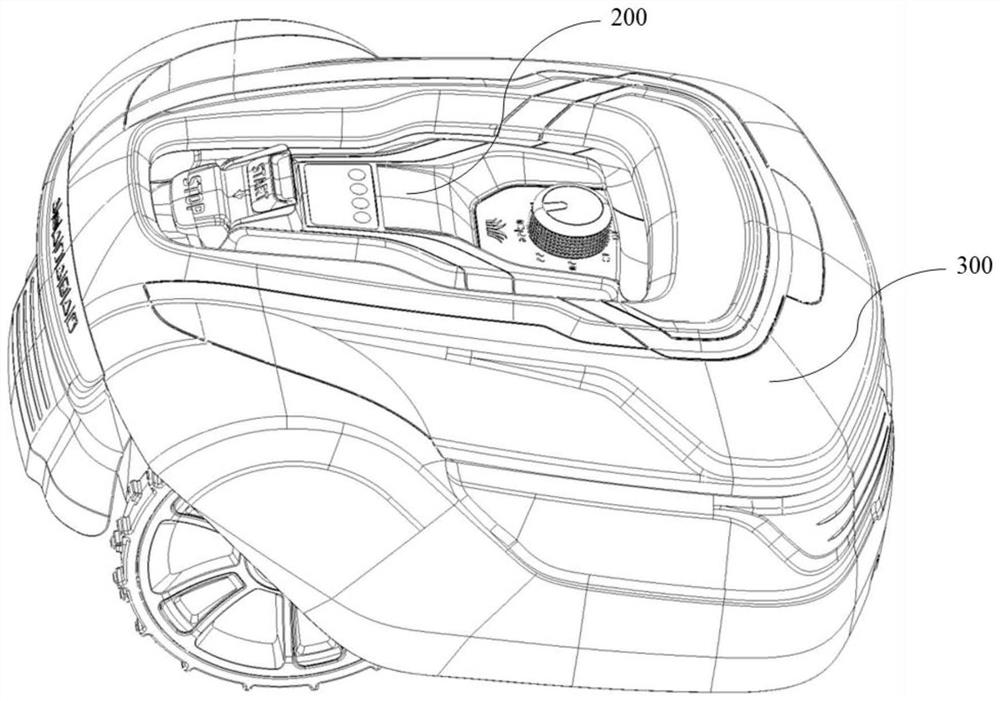
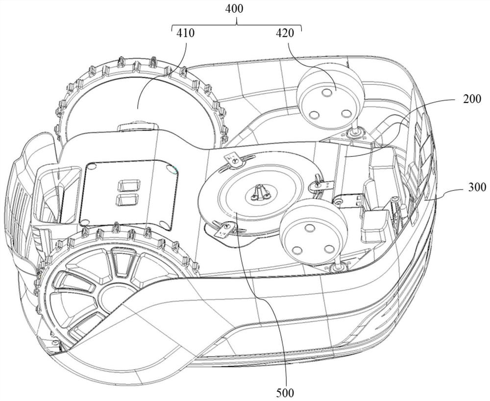
[0030] Such as figure 1 As shown, the present invention discloses a detection mechanism 100, including: a magnet module 110, located on the movable upper cover 300 of the lawnmower; a coil module 120, located on the casing 200 of the lawnmower; When the movable upper cover 300 of the lawn machine is displaced relative to the casing 200 , a relative movement occurs between the magnet module 110 and the coil module 120 , so that the coil module 120 produces a current change.

[0031] Optionally, in this case, the positions of the magnet module and the coil module can also be reversed, that is, the magnet module is located on the casing of the lawn mower, and the coil module is located on the movable upper cover of the lawn mower. Since the movable ...


PUM


Abstract

The invention provides a detection mechanism and a mower. The detection mechanism comprises a magnet module arranged on a movable upper cover, and a coil module positioned on a shell; and when relative displacement occurs between the movable upper cover and the shell, relative movement is generated between the magnet module and the coil module, so that the coil module generates the current change.Compared with the prior art, the detection mechanism is adopted to monitor the working state of the equipment, the coil module and the magnetic block module of the detection mechanism generate relative motion to generate corresponding signal current, and the specific motion state of the equipment is judged according to the direction of the generated signal current, so that corresponding adjustment is carried out; and the condition that the equipment is started under certain special conditions to trigger the alarm is avoided.

Description

technical field [0001] The invention relates to a detection mechanism and a lawn mower, which are mainly used for detecting the walking state of the lawn mower. Background technique [0002] The smart lawn mower is a robot for maintaining the lawn. It has the advantages of intelligence, modernization, environmental protection, and hands-free. It is more and more favored by the market and consumers. During the working process of the smart lawn mower, a series of sensors are needed to determine whether the machine is in a working state, among which the collision sensor and the lifting sensor are the most basic sensors to make it work normally. [0003] The currently widely used sensor is a magnet-Hall combination. When the device is started, the relative position between the magnet and the Hall needs to be in a triggered state. It is generally used to detect the static position between the magnet and the Hall. There are certain disadvantages in the detection of the collision ...

Claims


Application Information

Patent Timeline
Patent Type & Authority Applications(China)
IPC IPC(8): G01D5/20G01B7/02G01P13/02A01D34/00
CPCA01D34/008G01B7/02G01D5/2046G01P13/02
Inventor 李汪浩高杰曹金蒲志高
Owner CHANGZHOU GLOBE CO LTD
Why Eureka
Try Eureka