Bearing or thrust hobbing gear capable of achieving automatic clearance adjustment

An automatic adjustment and automatic adjustment technology, which is applied in the field of material mechanics and mechanics, can solve the problems of clearance or clearance reduction, changes in use conditions, and short life of workpieces.

Pending Publication Date: 2021-03-12
王踊
View PDF1 Cites 4 Cited by
  • Summary
  • Abstract
  • Description
  • Claims
  • Application Information

AI Technical Summary

Problems solved by technology

[0002] The bearings or thrust hobbing gears known to the public all have the defect that the clearance or clearance changes with the use conditions, the main reason is the change of load and the temperature difference of the workpiece caused by the heat generated by friction
The load change is mainly caused by the deformation of each part after being loaded; among the factors of temperature change, the heat dissipation conditions of the friction surface of the inner ring and the friction surface of the outer ring are usually different, resulting in low temperature of the outer ring and high temperature of the inner ring , the inner ring expands more from the radial direction outward, the outer ring expands less from the radial direction outward, and the gap between the inner and outer rings decreases. If it is a thrust hobbing gear or a rolling bearing, plus the thermal expansion of the rolling elements between the inner and outer rings , will lead to further reduction of clearance or clearance, which has a great impact on the accuracy, life and positioning of bearings or thrust hobbing gears, especially for thrust hobbing gears, due to the need to transmit thrust between rolling elements ( See Chinese patent: ZL 201820925392.6), so the clearance must be zero or negative, and the clearance cannot be greater than zero when the load increases, and the clearance will further decrease after the temperature difference occurs during operation, so the life of the workpiece is not long. publicize the solution to such problems

Method used


Image

  • Bearing or thrust hobbing gear capable of achieving automatic clearance adjustment
  • Bearing or thrust hobbing gear capable of achieving automatic clearance adjustment
  • Bearing or thrust hobbing gear capable of achieving automatic clearance adjustment

Examples


Embodiment Construction

[0055] Preferred embodiments of the present invention will be described with reference to the drawings.

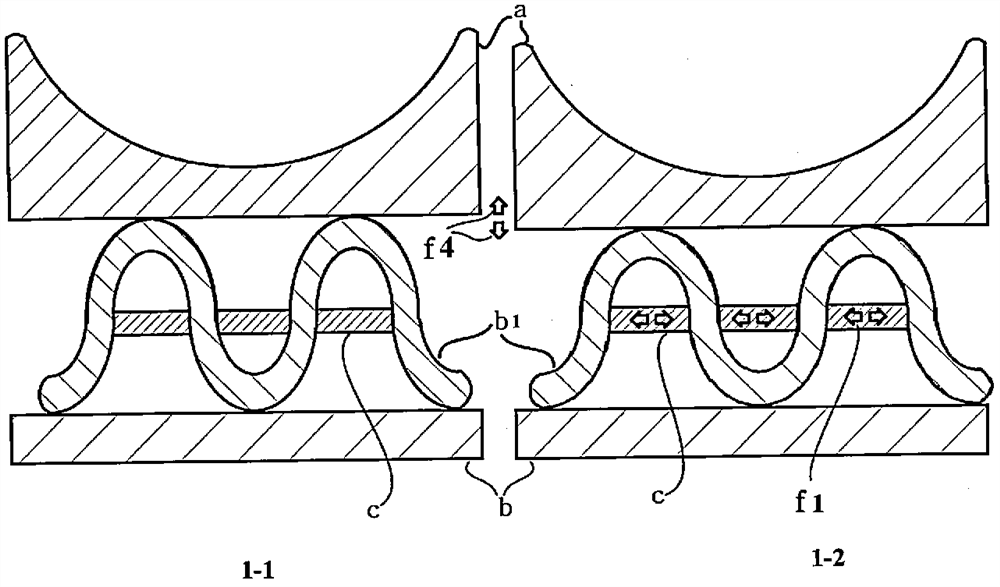
[0056] figure 1 It is a schematic diagram of the friction body support part as an independent part, and the deformation of the support part under the action of the automatic adjustment device leads to the change of the clearance. Picture 1-1 is before deformation, Figure 1-2 After deformation. Depend on Picture 1-1 It can be seen that the deformable friction body supporting part b1 supports the friction body a, so that the friction body is close to the direction of the friction surface body, compared with Figure 1-2 It can be seen that when the automatic adjustment device c expands to the left and right, the friction body support part b1 deforms to keep the friction body away from the friction surface; conversely, when the automatic adjustment device c shortens, the friction body deforms in the opposite direction.

[0057] figure 2 It is a schematic diagram of th...


PUM


Abstract

The invention discloses a bearing or thrust hobbing gear capable of achieving automatic clearance adjustment, and relates to the technical field of materials and machinery. The invention mainly aims to provide a technique for automatic clearance or gap adjustment, and the technique is applicable to the bearing or thrust hobbing gear so as to enable the bearing or thrust hobbing gear to have a relatively stable clearance or gap. According to the main technical scheme, through reasonable design of structures of friction bodies, temperature control deformation bodies or an electric device is usedfor enabling the friction bodies to deform or shift along with working conditions. Compared with known bearings or thrust hobbing gears, the bearing or thrust hobbing gear has the characteristics ofbeing more stable in clearance or gap, greater in bearable limit rotating speed, smoother in operation, higher in precision, and the like. The technique for automatic clearance adjustment is applicable to sliding bearings, rolling bearings, thrust hobbing gears and other mechanical devices requiring automatic clearance adjustment.

Description

technical field [0001] The invention relates to material mechanics and mechanics, and belongs to the field of mechanical technology. Background technique [0002] The currently known bearings or thrust hobbing gears all have the defect that the clearance or clearance changes with the use conditions. The main reason is that the temperature difference of the workpiece is caused by the change of the load and the heat generated by friction. The load change is mainly caused by the deformation of each part after being loaded; among the factors of temperature change, the heat dissipation conditions of the friction surface of the inner ring and the friction surface of the outer ring are usually different, resulting in low temperature of the outer ring and high temperature of the inner ring , the inner ring expands more from the radial direction outward, the outer ring expands less from the radial direction outward, and the gap between the inner and outer rings decreases. If it is a ...

Claims


Application Information

Patent Timeline
IPC IPC(8): F16C25/04F16C25/08F16H57/12
CPCF16C25/04F16C25/08F16H57/12F16H2057/123
Inventor 王踊
Owner 王踊
Why Eureka
Try Eureka