Steel bar machining protective shed convenient to disassemble and assemble

A technology for steel bar processing and protective sheds, applied in industrial buildings, buildings, building structures, etc., can solve the problems of different sizes of protective sheds, troublesome assembling of protective sheds, waste of wood, etc., to optimize appearance, save materials, and improve work. The effect of efficiency

Pending Publication Date: 2021-03-12
中建新疆建工集团第一建筑工程有限公司
View PDF0 Cites 0 Cited by
  • Summary
  • Abstract
  • Description
  • Claims
  • Application Information

AI Technical Summary

Problems solved by technology

[0002] Processing steel bars in construction projects requires the deployment of many qualified and safe steel bar processing plants. In this process, the protection work during steel bar processing is particularly critical. Traditional steel bar processing shelters are difficult to assemble, difficult to disassemble, and difficult to repair after damage. Difficult turnover, waste of wood and other unfavorable conditions, and there are problems such as different sizes of traditional steel bar processing sheds, which are neither neat nor beautiful

Method used


Image

  • Steel bar machining protective shed convenient to disassemble and assemble
  • Steel bar machining protective shed convenient to disassemble and assemble
  • Steel bar machining protective shed convenient to disassemble and assemble

Examples


Embodiment Construction

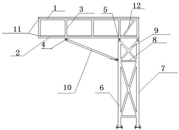
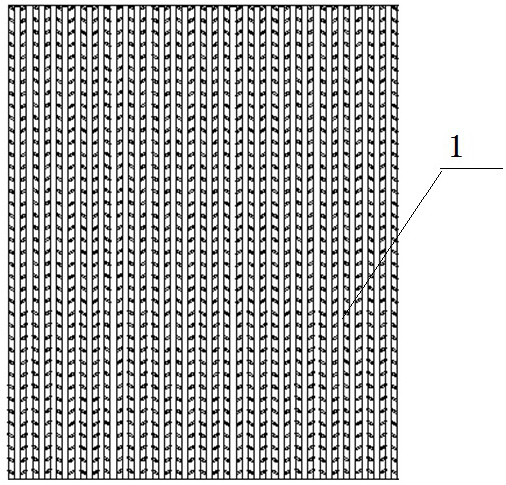
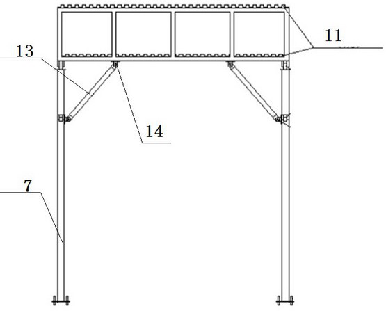
[0014] A steel bar processing protective shed that is easy to disassemble, such as figure 1 , figure 2 , image 3 As shown, the upper frame 1 and the lower frame 2 are made of steel, and the upper and lower frames 1 and 2 are fixedly connected by the vertical rods 3 evenly distributed along their four sides to form an upper scaffolding. A symmetrical front pin seat 4 and two symmetrical side pin seats 5 are respectively arranged on the bottom surface, two symmetrical rear pin seats 14 are respectively arranged on the bottom surface of the rear frame of the lower frame, and front and rear columns 6, 7 are combined and fixed together by cross brace 8 and scissors brace 9 to form a composite column. The bottom plates set at the lower ends of the front and rear columns 6 and 7 are fixed to the ground foundation through bolts, and the connecting lugs set at the upper ends are fixed through pin shafts. Connected with the side pin seat 5 of the upper scaffold, the first diagonal s...


PUM

PropertyMeasurementUnit
Lengthaaaaaaaaaa
Widthaaaaaaaaaa
Thicknessaaaaaaaaaa

Abstract

The invention discloses a steel bar machining protective shed convenient to disassemble and assemble. The steel bar machining protective shed comprises an upper frame and a lower frame which are madeof steel, wherein the upper frame and the lower frame are fixedly connected into a whole through vertical rods to form an upper shed frame; front pin shaft seats and two side pin shaft seats are arranged on the bottom surfaces of two side frames of the lower shed frame; two rear pin shaft seats are arranged on the rear frame of the lower frame; front stand columns and rear stand columns are fixedly connected together through cross braces and diagonal braces; bottom plates arranged at the lower ends of the front stand columns and the rear stand columns are fixedly connected with a ground foundation through bolts; connecting lugs arranged at the upper ends of the front stand columns and the rear stand columns are connected with the side pin shaft seats of the upper shed frame; first diagonalbraces are hinged to the upper portions of the front stand columns; connecting lugs arranged at the upper ends of the first diagonal braces are connected with the front pin shaft seats of the upper shed frame; second diagonal braces are hinged to the upper portions of the rear stand columns; and connecting lugs at the upper ends of the second diagonal braces are connected with the rear pin shaftseats of the upper shed frame. The steel bar machining protective shed is reasonable in structure, safe, reliable, convenient to disassemble and assemble and capable of being repeatedly used, the construction efficiency of a steel bar field is improved, the working efficiency is improved, the appearance of the protective shed of the steel bar field is optimized, and the wood loss is reduced.

Description

technical field [0001] The invention belongs to the improvement of the structure of a steel bar processing protective shed on a construction site, in particular to a steel bar processing protective shed which is easy to disassemble. Background technique [0002] Processing steel bars in construction projects requires the deployment of many qualified and safe steel bar processing plants. In this process, the protection work during steel bar processing is particularly critical. Traditional steel bar processing protective sheds are troublesome to assemble, difficult to disassemble, and difficult to repair after damage. Difficult turnover, waste of wood and other unfavorable conditions, and there are problems such as different sizes of traditional steel bar processing sheds, which are neither neat nor beautiful. Contents of the invention [0003] The purpose of the present invention is to provide a protective shed for steel bar processing that is easy to disassemble and assemb...

Claims


Application Information

Patent Timeline
IPC IPC(8): E04H5/02E04B1/19E04B1/343
CPCE04B1/19E04B1/343E04H5/02
Inventor 车海宝陈贵勇杜长伟陈海涛唐素梅于宏桥杨敬龙李岩刘涛田子航李同同
Owner 中建新疆建工集团第一建筑工程有限公司
Why Eureka
Try Eureka