Plate overturning device for wood floor processing

A technology for wooden floors and flaps, applied in wood processing equipment, manufacturing tools, etc., can solve problems such as low efficiency and manpower consumption, and achieve the effects of reducing production costs, high applicability, and improving production efficiency

Inactive Publication Date: 2021-03-05
怀宁县三兴木业有限公司
View PDF6 Cites 2 Cited by
  • Summary
  • Abstract
  • Description
  • Claims
  • Application Information

AI Technical Summary

Problems solved by technology

[0004] The purpose of the present invention is to solve the problems of labor-intensive and low efficiency in the prior art, and propose a turning device for wood floor processing

Method used


Image

  • Plate overturning device for wood floor processing
  • Plate overturning device for wood floor processing
  • Plate overturning device for wood floor processing

Examples


Embodiment 1

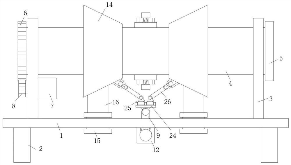
[0026] refer to Figure 1-3 , a kind of turnover device for wood floor processing, comprising workbench 1, both sides of the top of workbench 1 are fixedly connected with riser 3, and the board body of riser 3 is provided with horizontal round hole 1, and the two riser 3 The material transfer cylinder 4 is installed in rotation, and the two ends of the material transfer cylinder 4 respectively pass through the horizontal hole 1, and the outer side of one end of the material transfer cylinder 4 is fixedly connected with the limit ring 5, and the outer side of the other end is fixedly connected with the active ring 5. Gear 8, one side of the vertical plate 3 is fixedly equipped with a motor 7 by bolts, the output shaft of the motor 7 is fixedly connected with a driving gear 8, and the driving gear 8 is meshed with the driven gear ring 6. The vertical plate 9 is fixedly installed on the side, and the rotating rod 10 is installed in rotation between the vertical plates 9. The rota...

Embodiment 2

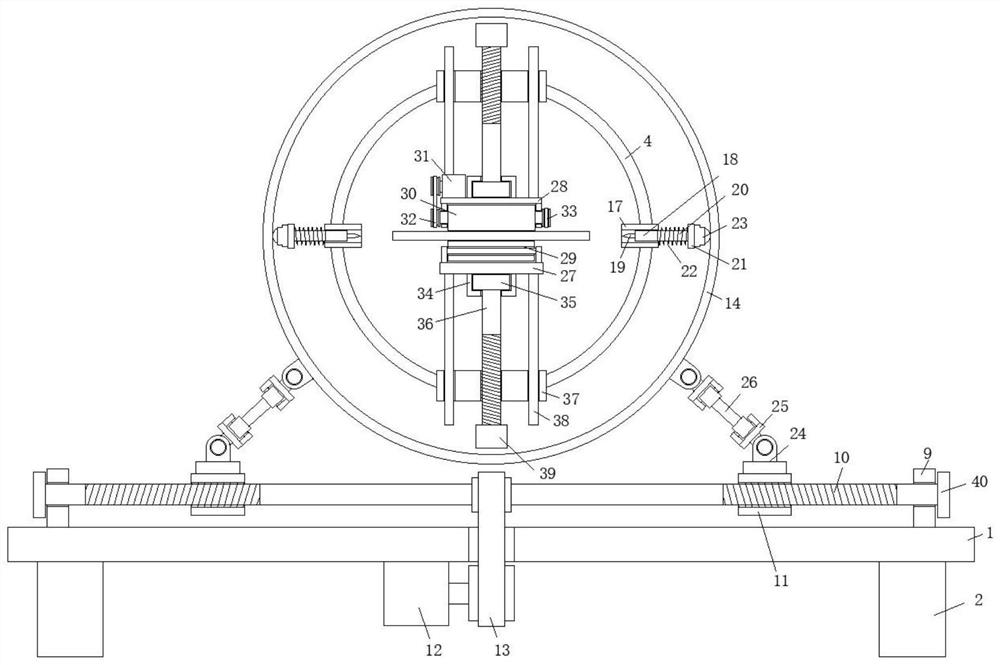
[0030] Such as Figure 1-3 As shown, this embodiment is basically the same as Embodiment 1. Preferably, the rotating sleeves 34 are respectively fixedly connected to the sides of the horizontal plate 1 27 and the horizontal plate 2 28 away from each other, and the top and bottom of the cylinder 4 are both Be provided with installation hole ratio and fixedly install lath 37 respectively, the plate body of lath 37 is provided with slide hole and threaded hole, and one end of slide rod 38 passes in the slide hole, and the other end is connected with horizontal plate one 27 and horizontal plate two 28 respectively. Fixedly connected, one end of the threaded shaft 36 is threaded through the threaded hole, and the other end of the threaded shaft 36 is coaxially fixedly connected with the circular plate 35 .

[0031] In this embodiment, the lengths of the first horizontal plate 27 and the second horizontal plate 28 are equal to the length of the transfer cylinder 4. After the flippin...

Embodiment 3

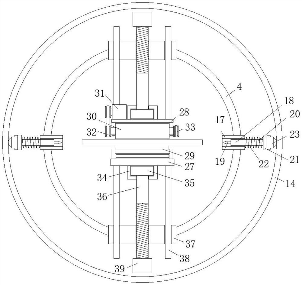
[0033] Such as Figure 1-3 As shown, this embodiment is basically the same as Embodiment 1. Preferably, one end of the threaded shaft 36 is fixedly connected with a knob 39 , and the outer side of the knob 39 is provided with anti-slip grooves.

[0034] In this embodiment, the setting of the knob 39 greatly facilitates the twisting of the threaded shaft 36 by people, which is labor-saving and convenient.


PUM


Abstract

The invention discloses a plate overturning device for wood floor processing. The plate overturning device for wood floor processing comprises a worktable. Vertical plates are fixedly connected to twosides of the top of the worktable, horizontal round holes I are formed in the plate bodies of the vertical plates, a material transfer cylinder is rotatably mounted between the two vertical plates, two ends of the material transfer cylinder penetrate through the horizontal round holes I separately, a limiting ring is fixedly connected to the outer side of one end of the material transfer cylinder, a driving gear is fixedly connected to the outer side of the other end, a motor I is fixedly mounted on one side of the vertical plate through bolts, a driving gear is fixedly connected to an outputshaft of the motor I, the driving gear is in engaged connection with a driven gear ring, and risers are fixedly mounted on two sides of the top of the worktable. The plate overturning device for woodfloor processing brings convenience to people to overturn the panel in a panel processing course, so that the production efficiency is improved greatly. The panel is protected, and the panel is collected conveniently after being overturned. The plate overturning device for wood floor processing is high in adaptability, reduces the production cost and meets a using demand of people in production and life.

Description

technical field [0001] The invention relates to the technical field of board processing equipment, in particular to a panel turning device for processing wooden floors. Background technique [0002] Wooden floor refers to the floor made of wood. Wooden flooring produced in China is mainly divided into six categories: solid wood flooring, laminate flooring, solid wood composite flooring, multi-layer composite flooring, bamboo flooring and cork flooring, as well as the emerging wood-plastic flooring. . [0003] During the processing of wood floors, it is often necessary to process both sides of the board. Therefore, between each process and station, the board in progress needs to be turned over. The existing turning process is mostly done manually. , a small part is through machinery, using gravity to block on one side of the plate during the falling process of the plate, so as to achieve relatively labor-saving completion of the plate flip, but this method often causes damag...

Claims


Application Information

Patent Timeline
IPC IPC(8): B27M3/04
CPCB27M3/04
Inventor 陈小根
Owner 怀宁县三兴木业有限公司
Why Eureka
Try Eureka