
Connection structure for communication port and pipe end, opening/closing valve device, and removal jig

A connection structure, open and close valve technology, applied in the direction of valve device, valve shell structure, valve details, etc., can solve the problem of low replaceability of sealing parts, achieve the effect of improving replaceability and easy disassembly

Active Publication Date: 2021-02-26
NERIKI KK +1
View PDF9 Cites 0 Cited by
  • Summary
  • Abstract
  • Description
  • Claims
  • Application Information

AI Technical Summary

Problems solved by technology

[0004]However, as shown in Patent Document 1, when the sealing member is attached to the mounting groove (stepped portion), it is different from the case of arranging the sealing member only at the joint portion. In contrast, although the seal member can be arranged at an appropriate position, it is difficult to remove the seal member in the mounted state from the mounting groove, and the replaceability of the seal member is low.

Method used


Image

  • Connection structure for communication port and pipe end, opening/closing valve device, and removal jig
  • Connection structure for communication port and pipe end, opening/closing valve device, and removal jig
  • Connection structure for communication port and pipe end, opening/closing valve device, and removal jig

Examples


Embodiment Construction

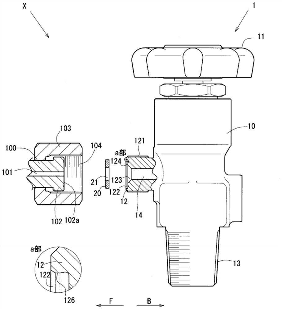
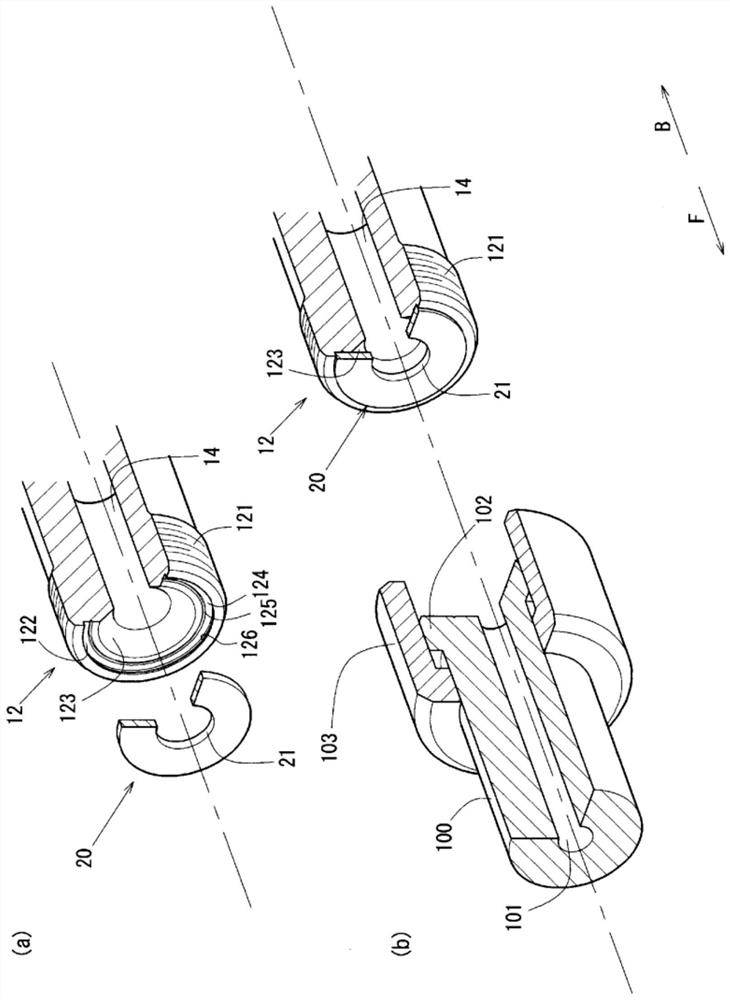
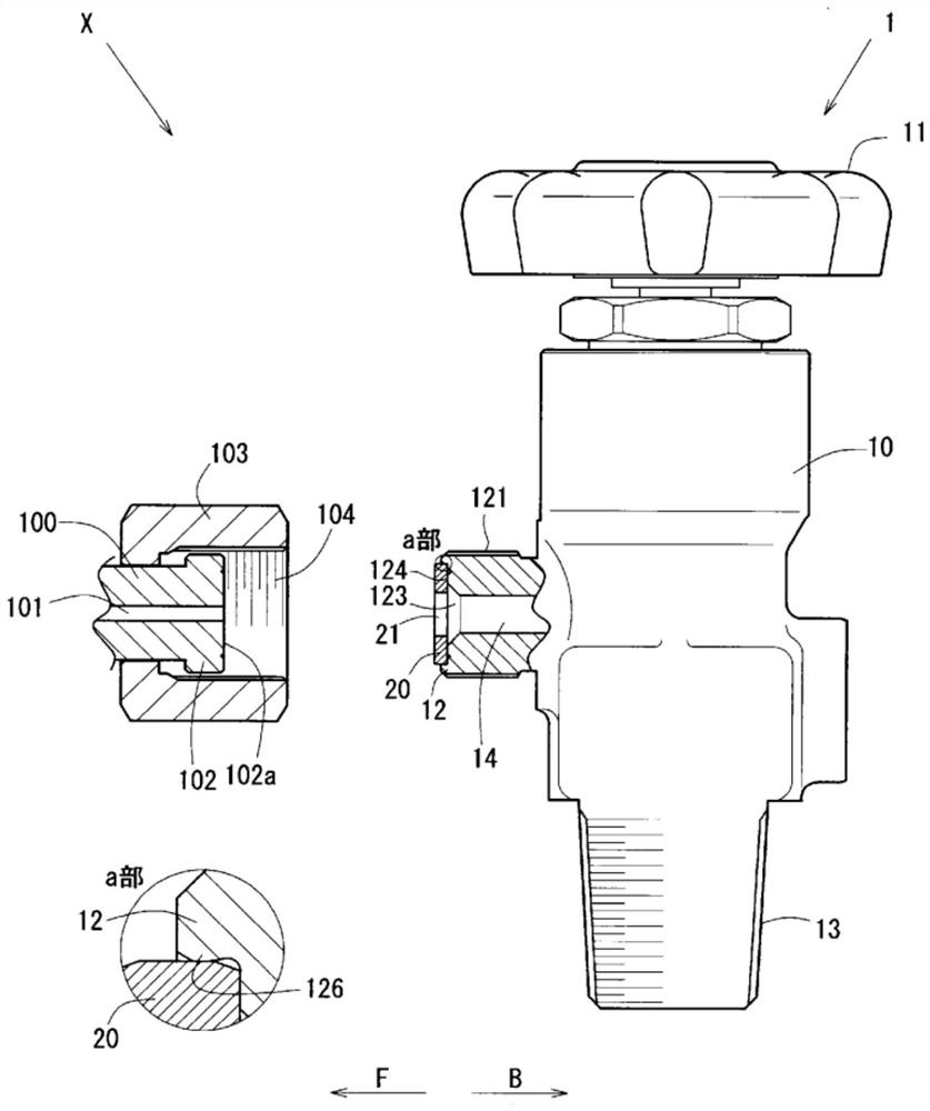
[0050] refer to Figure 1 to Figure 7 , the connection structure X between the container valve device 1 and the flow pipe 100 as one embodiment of the present invention and the detachment of the gasket 20 mounted in the mounting groove 122 will be described.

[0051] figure 1 , image 3 and Figure 4 It is a partially cutaway schematic front view showing the connection structure X between the container valve device 1 and the flow piping 100, figure 2 It is a partial cross-sectional schematic explanatory diagram showing the connection structure X between the conduction port 12 and the flow pipe 100 of the container valve device 1 . Figure 5 It is a partially cutaway schematic perspective view showing the connection structure X between the conduction port 12 of the container valve device 1 and the flow pipe 100, Figure 6 It is a perspective view showing the removal jig 200 . Figure 7 It is a partial cross-sectional schematic front view showing a state where the packing ...


PUM


Abstract

The purpose of the present invention is to provide a connection structure for a communication port and a pipe end, an opening / closing valve device, and a removal jig, wherein a sealing member that canbe disposed at an appropriate position while the communication port and the pipe end are connected can be easily replaced. This connection structure X in a container valve device 1 having an opening / closing valve for switching between opening and closing in an intermediate portion of a flow passage 14 through which gas flows is a connection structure for a communication port 12, which constitutesone end of the flow passage 14, and a pipe end section 102 of a flow passage pipe 100 through which gas flows. The communication port 12 and the pipe end section 102 are arranged to abut each other.A ring-like gasket 20 having an opening 21 with a diameter equal to or greater than the diameter of the flow passage 14 is arranged between the communication port 12 and the pipe end section 102. An attachment groove 122 for attaching the gasket 20 so that a portion of the gasket protrudes toward the tip side F is formed in the communication port 12. A tapered space 123, into which a lateral protrusion section 203a of a removal jig 200 can be inserted, is provided on the body side B of the communication port 12.

Description

technical field [0001] The present invention relates to, for example, an on-off valve device having an on-off valve that can be switched on and off in the middle of a gas-conducting flow path. The connection structure of the pipe end, the on-off valve device, and the removal jig for removing the sealing member attached to the on-off valve device. Background technique [0002] In general, an on-off valve device is provided for switching between an open state and a sealed state, and a conduction port as one end of a flow path is connected to a pipe end of the flow path piping to conduct a fluid such as gas. At this time, as shown in Patent Document 1, an annular sealing member (gasket) is disposed between the conduction port and the pipe end to prevent leakage of gas from the joint between the conduction port and the pipe end. [0003] Since such a sealing member is installed in a pressurized state to obtain high sealing performance, it may deteriorate due to use and the seal...

Claims


Application Information

Patent Timeline
IPC IPC(8): F16J15/00F16K27/00
CPCF16K27/00F16J15/00F16J15/10F17C13/04
Inventor 冈田慎司高田幸治西村康雄高根沢敏
Owner NERIKI KK
Learn More