A low-level beam transport vehicle

A low-position technology for beam-carrying vehicles, applied in the field of low-position beam-transporting vehicles, can solve problems such as longitudinal position conflicts, traction system installation position conflicts, and long moving distances of rear beam trolleys, thereby reducing costs, simplifying product structures, and reducing bearing costs. The effect of height

Active Publication Date: 2021-09-24
HAN JIANG HEAVY IND CO LTD 11TH BUREAU GRP CRCC +1
View PDF1 Cites 0 Cited by
  • Summary
  • Abstract
  • Description
  • Claims
  • Application Information

AI Technical Summary

Problems solved by technology

[0004] However, the applicant found that there is still room for optimization and improvement in this product during use: since the front load beam trolley and the rear load beam trolley adopt the same structure, move on the same track, and use the same traction system for traction, so As a result, there is a conflict between the longitudinal positions of the two along the direction of the main beam, and there is also a conflict in the installation position of the traction system corresponding to the two on the frame. As a result, the front load beam trolley can only move in the front section of the frame, and the rear load beam trolley can only move at the front of the frame. The beam trolley can only move at the rear of the frame, and there is a dividing line between the two movable ranges
Usually, during the beam feeding process of the bridge erecting machine, the moving distance of the front loading beam trolley is relatively short, but the moving distance of the rear loading beam trolley is relatively long, and the rear loading beam trolley needs to cooperate with the front lifting trolley of the bridge erecting machine to lift the box girder They are sent to the beam taking position of the rear lifting trolley, that is, the rear loading beam trolley needs to be able to move forward as much as possible (to obtain a larger moving range), but due to the obstruction of the front loading beam trolley and the traction system of the front loading beam trolley, The rear beam trolley cannot move too far forward, which brings a lot of inconvenience to the use process

Method used


Image

  • A low-level beam transport vehicle
  • A low-level beam transport vehicle
  • A low-level beam transport vehicle

Examples


Embodiment Construction

[0032] The present invention will be described in detail below in conjunction with the accompanying drawings and specific embodiments, but the protection scope of the present invention is not limited to the following embodiments.

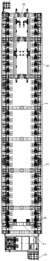
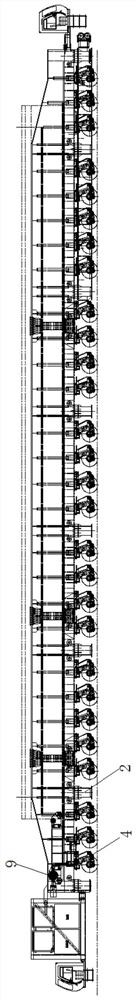
[0033] The low-position beam transport vehicle provided by the present invention has an overall structure such as figure 1 with figure 2 As shown, it includes the frame 1 and the telescopic outrigger 2 installed on the frame, the box beam jacking cylinder 3, the suspension running assembly 4, the steering cylinder, the driver's cab 5, the electrical system and the hydraulic system, and the front section of the frame The front pack beam dolly 6, the back pack beam dolly 7 positioned at the rear section of the vehicle frame, the front traction system 8 for driving the front pack beam dolly and the rear traction system 9 for driving the back pack beam dolly. Among the above components, telescopic outriggers, box girder jacking cylinders, suspension t...


PUM


Abstract

The invention provides a low-position beam transport vehicle. The lower part of the inner wall between two main beams is provided with a step-like walking step. The walking beams are respectively fixed at the left and right ends of the crossbeam of the rear trolley. The bottom of the walking beam is located on the walking steps. The front and rear ends of the walking beam are connected with the rear traction system; The connecting beam is fixed under the cross beam of the rear trolley. The front beam trolley and the rear beam trolley of the low-position beam transporter move longitudinally at different heights and along different tracks, and the traction systems used by the two are also installed on the frame at different heights, so this In the invention, the supporting height of the supporting box girder can be effectively reduced to make it easier to pass through the tunnel, and the longitudinal movement range of the rear beam trolley is expanded, making it more flexible in the working process of transporting and feeding the beam.

Description

technical field [0001] The invention belongs to the technical field of bridge construction machinery and methods, and in particular relates to a low-level beam transport vehicle suitable for transporting different box girders. Background technique [0002] There are two main types of beam transport vehicles currently in use: tunnel beam transport vehicles and tunnel beam transport vehicles, also known as high beam transport vehicles and low beam transport vehicles. The structures of the two types of beam transport vehicles are basically the same: they both use a frame with the main girder placed in the middle, tire groups are distributed longitudinally and evenly on both sides of the main girder, and are fully hydraulically driven. The difference is that high-position beam transport vehicles usually use large-size tires to reduce the number of bearing axles while meeting the beam transport conditions, but the height of the beam transport is high, and it is difficult to trans...

Claims


Application Information

Patent Timeline
Patent Type & Authority Patents(China)
IPC IPC(8): B60P3/022E01D21/00
CPCB60P3/00E01D21/00
Inventor 张光明郝永刚梅慧浩唐坤元杜小刚苏六帅邓博曹翠王嵽显
Owner HAN JIANG HEAVY IND CO LTD 11TH BUREAU GRP CRCC
Why Eureka
Try Eureka