Anastomat tissue clamping piece capable of stably clamping tissue

A tissue and stapler technology, which is applied in the field of staplers, can solve the problems of single function, excessive pressing of nail sleeves, and inability to achieve stable clamping of tissue for anastomosis and suturing, so as to achieve the effect of anastomosis

Pending Publication Date: 2021-02-12
WUXI BM PRECISION PARTS CO LTD
View PDF8 Cites 0 Cited by
  • Summary
  • Abstract
  • Description
  • Claims
  • Application Information

AI Technical Summary

Problems solved by technology

[0003] In the patent No. CN201010197189.X, the patent name is a minimally invasive surgical anastomosis device, which records that: the working head can penetrate into the patient's body for minimally invasive anastomosis, and can be applied to suturing tissue wounds with complex shapes. It solves the shortcomings of the single use function of the anastomotic instruments used in minimally invasive surgery
[0004] However, in the prior art, the connecting rod and the bottom plate are mostly integral and non-detachable structures, and the length of the connecting rod is not easy to adjust according to the use requirements; when the nailing sleeve is moved to press the nail, it is easy to cause excessive pressing or the nail sleeve is separated from the nail. In addition, it is not easy to grasp the strength during the process of moving the nail sleeve, and it is not easy to make the nail sleeve advance stably, so it is impossible to achieve stable clamping of tissue and anastomotic suture work

Method used


Image

  • Anastomat tissue clamping piece capable of stably clamping tissue
  • Anastomat tissue clamping piece capable of stably clamping tissue
  • Anastomat tissue clamping piece capable of stably clamping tissue

Examples


Embodiment Construction

[0038] The following will clearly and completely describe the technical solutions in the embodiments of the present invention with reference to the accompanying drawings in the embodiments of the present invention. Obviously, the described embodiments are only some, not all, embodiments of the present invention. Based on the embodiments of the present invention, all other embodiments obtained by persons of ordinary skill in the art without making creative efforts belong to the protection scope of the present invention.

[0039] see Figure 1-Figure 7 Shown:

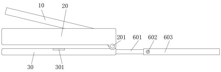
[0040] figure 1 It is one of the structural schematic diagrams in the embodiment of the present invention;

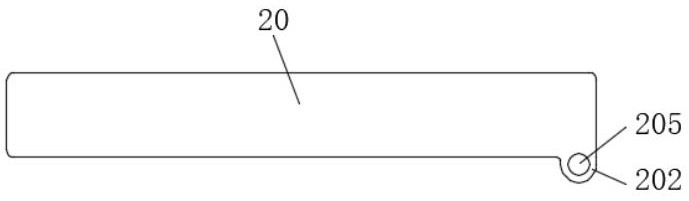
[0041] figure 2 It is a structural schematic diagram of the pressing plate in the embodiment of the present invention;

[0042] image 3 It is a structural schematic diagram of the staple cartridge in the embodiment of the present invention;

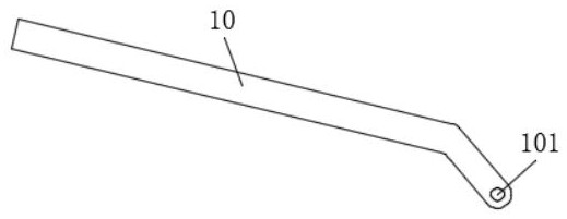
[0043] Figure 4 It is a structural schematic diagram of the bot...


PUM


Abstract

The invention belongs to the technical field of anastomats, and discloses an anastomat tissue clamping piece capable of stably clamping tissue, which comprises a body, a pressing plate, a nail bin anda bottom plate, a bent section is integrally formed at one end of the pressing plate, and a first through hole is formed in the end of the bent section; a first boss is integrally formed at one end of the nail bin, and a second through hole is formed in the first boss; a second boss is integrally formed at one end of the bottom plate, a third through hole is formed in the second boss, and a threaded hole is formed in the end, close to the second boss, of the bottom plate; one end of the threaded hole is connected with a connecting rod, the connecting rod comprises an inner rod, a fixing pieceand a sleeve, the inner rod extends from the interior of the sleeve to the exterior of the sleeve, and the inner rod is connected with the sleeve through the fixing piece; when the pressing plate ispressed downwards, the pressing block slides in the sliding groove, the pressing block is limited through the sliding groove, and excessive pressing is prevented.

Description

technical field [0001] The invention belongs to the technical field of staplers, in particular to a tissue clamping part for a stapler that can stably clamp tissue objects. Background technique [0002] Vascular anastomosis is a difficult operation, and the operator needs to undergo a long-term rigorous training. This surgical method is widely used in free flap reconstruction of defects, replantation of severed limbs, and vascular reconstruction. The quality of vascular anastomosis is the key to the success of the operation. Many studies have shown that compared with traditional microvascular sutures, the speed of anastomosis with anastomotic instruments is 4-5 times faster, the strength of anastomosis is sufficient, and the patency rate can reach almost 100%. According to different materials, there are five types of vascular staplers: ring nails, clips, adhesives, stents, and laser welding. At present, the most successful clinical application is ring nails. [0003] In th...

Claims


Application Information

Patent Timeline
Patent Type & Authority Applications(China)
IPC IPC(8): A61B17/115
CPCA61B17/115A61B2017/00778A61B2017/1107
Inventor 浦晓冬
Owner WUXI BM PRECISION PARTS CO LTD
Why Eureka
Try Eureka