
Particle filter tracking method based on infrared saliency feature fusion

A technology of feature fusion and particle filtering, applied in the field of image processing

Active Publication Date: 2021-02-09
HARBIN INST OF TECH AT WEIHAI
View PDF10 Cites 2 Cited by
  • Summary
  • Abstract
  • Description
  • Claims
  • Application Information

AI Technical Summary

Problems solved by technology

Finally, the target template is updated by adaptive discrimination

Method used


Image

  • Particle filter tracking method based on infrared saliency feature fusion
  • Particle filter tracking method based on infrared saliency feature fusion
  • Particle filter tracking method based on infrared saliency feature fusion

Examples


Embodiment Construction

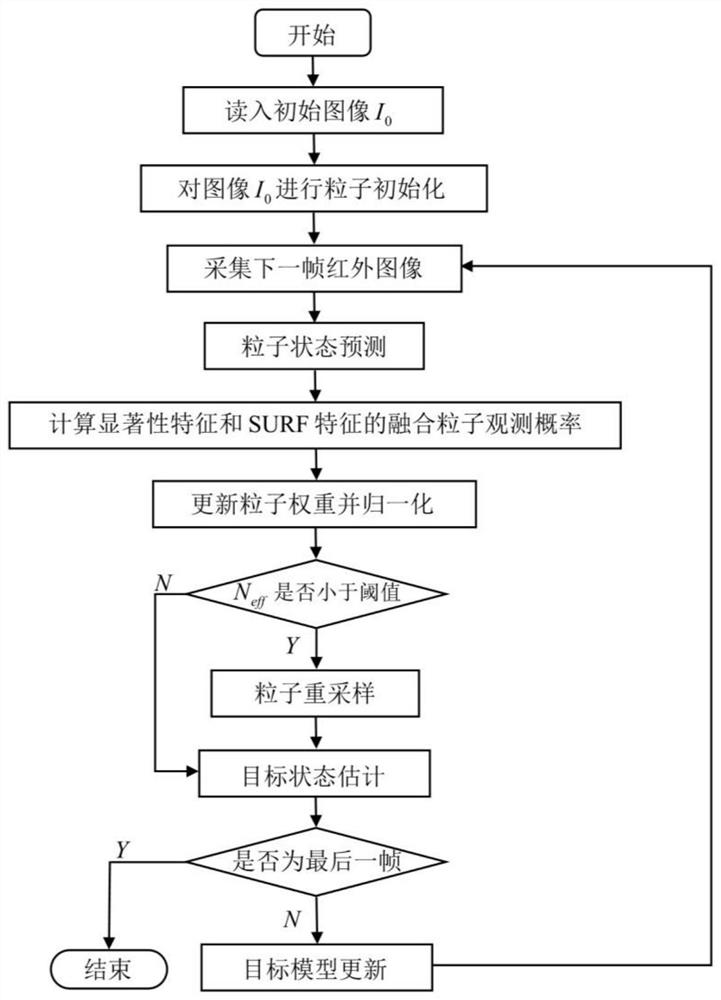
[0083] 1: read frame 0 image I 0 , and for image I 0 Perform particle initialization, the specific operation process is as follows:

[0084] (a) Use a width w 0 and height is h 0 A rectangular box fits the image I 0 The target to be tracked in , get the target state X at the initial moment 0 =[x 0 ,y 0 ,w 0 ,h 0 ] and with (x 0 ,y 0 ) as the center of the target area temp to be tracked 0 (width is w 0 , the height is h 0 );

[0085] (b) With the initial state of the target as the center, N independent and identically distributed samples are randomly generated within the range of the propagation radius r, so as to obtain the initial particle set And the set of target areas to be tracked at the initial moment in represents the image I 0 In the initial particle set X 0 The position coordinates of the i-th particle in Centered target area to be tracked (width is high for ), set the initial particle weight as Wherein i=1,2,...,N represents the label of ...


PUM


Abstract

The invention relates to a particle filter tracking method based on infrared significance feature fusion. A particle filtering framework is adopted, a corresponding feature observation model is established in a multi-feature fusion mode to calculate particle weights, the position information and the weights of the particles are used for obtaining an estimated target state to achieve target tracking, and the figure 1 in the abstract figure of the specification is a specific implementation flow chart of the invention.

Description

Technical field: [0001] The invention belongs to the field of image processing, and specifically combines multi-feature fusion and particle filtering to obtain accurate estimation of target motion. Background technique: [0002] According to the different target model establishment, the common target tracking algorithms can be divided into two methods: generative and discriminative. Tracking before detection methods applied to sequential images mainly include pipeline filtering, dynamic programming, multi-level hypothesis testing, 3D matched filtering, particle filtering, etc. Pipeline filtering is a commonly used method based on multi-frame image analysis. It takes the suspicious target position of each frame as the center and divides a cross-sectional area. When the error between the number of targets in this area and the number of real targets is within a certain range, it is judged as The parameters that the algorithm needs to consider include the shape and size of the ...

Claims


Application Information

Patent Timeline
Patent Type & Authority Applications(China)
IPC IPC(8): G06T7/246G06T7/277
CPCG06T7/251G06T7/277
Inventor 王好贤陈雅婷谢飞周志权王军
Owner HARBIN INST OF TECH AT WEIHAI
Learn More